Motor speed control system and method thereof

a technology of motor speed control and control system, which is applied in the direction of dynamo-electric converter control, mechanical equipment, dynamo-electric converter control, etc., can solve the problems of increased manufacturing cost of motors, too large power consumption of motors, and long time-consuming to reach predetermined values of rotational speed

Inactive Publication Date: 2017-07-04
HANKING POWER TECH
View PDF15 Cites 0 Cited by
  • Summary
  • Abstract
  • Description
  • Claims
  • Application Information

AI Technical Summary

Benefits of technology

[0039]3. The system and method of the present disclosure can weaken the magnetism of the rotor and reduce the hysteresis effect of the motor for saving the energy. Moreover, the system and method of the present disclosure can further increase rotor speed over the predetermined value by the control module.

Problems solved by technology

However, the permanent magnet motor has the characteristics of slow starting time, and has insufficient torque at low speed, therefore its rotational speed takes a long time to reach a predetermined value.
Furthermore, a complicated control system is required in the permanent magnet motor, thus the manufacturing cost of the motor is increased.
Moreover, when the permanent magnet motor reaches the highest rotor speed, the power consumption of the motor is too large.

Method used


Image

  • Motor speed control system and method thereof
  • Motor speed control system and method thereof
  • Motor speed control system and method thereof

Examples


Embodiment Construction

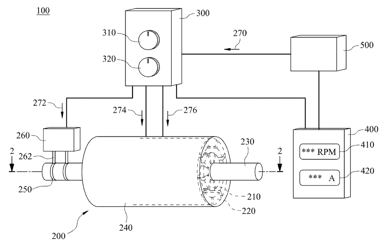
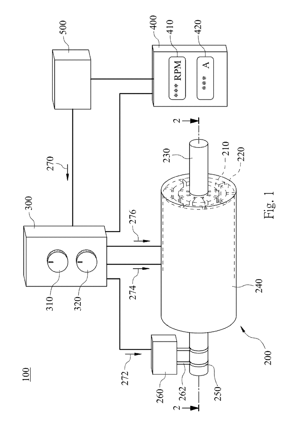
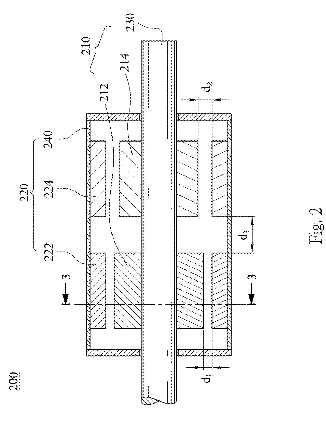
[0019]FIG. 1 is a schematic view of a motor speed control system according to one embodiment of the present disclosure; FIG. 2 is a cross-sectional view of the motor of FIG. 1; FIG. 3A is a lateral view of the rotor of FIG. 2; and FIG. 3B is a cross-sectional view of the motor of FIG. 2. In FIG. 1, the motor speed control system 100 includes a motor 200, a control module 300, a displaying module 400 and a power supply 500.

[0020]In detail, the motor 200 includes a rotor 210, a stator 220, two slip rings 250 and a brush assembly 260. The rotor 210 includes a rotational axis 230, an induction rotor portion 212 and a permanent magnet rotor portion 214. The stator 220 includes a shell 240, an induction stator portion 222 and a permanent magnet stator portion 224. The stator 220 is located outside of the rotor 210. The induction rotor portion 212 is corresponding to the induction stator portion 222. The induction rotor portion 212 and the induction stator portion 222 are separated by an i...


PUM


Abstract

A motor speed control system includes a motor, a control module and a displaying module. The motor includes a rotor and a stator. The rotor includes at least one induction rotor portion. The stator includes at least one induction stator portion. The induction rotor portion is corresponding to the induction stator portion. The control module is electrically connected to the rotor and the stator. The control module controls an induction rotor current of the induction rotor portion and an induction stator current of the induction stator portion to produce a rotor speed. The control module decreases or turns off the induction rotor current to keep the rotor speed at a predetermined value according to a rotational inertia of the rotor and the induction stator current when the rotor speed reaches the predetermined value. The displaying module displays the rotor speed and variable currents.

Description

RELATED APPLICATIONS[0001]This application claims priority to Taiwan Application Serial Number 103203039 filed Feb. 21, 2014 and Taiwan Application Serial Number 104100775, filed Jan. 9, 2015, which are herein incorporated by reference.BACKGROUND[0002]Technical Field[0003]The present disclosure relates to a motor speed control system and a motor speed control method. More particularly, the motor speed control system and the motor speed control method of the present disclosure are capable of reducing magnetic force of a rotor and increasing motor operation efficiency.[0004]Description of Related Art[0005]In many industrials, operations of machines require a rotational movement. A motor is commonly used to produce this kind of rotational movement. The motor has become an indispensable device owing to its capability on converting magnetic energy or electrical energy into mechanical energy. There are various types of motors that can be applicable to different environments and operation ...

Claims


Application Information

Patent Timeline
Patent Type & Authority Patents(United States)
IPC IPC(8): F16H48/06H02K16/00H02P25/22H02P6/08H02P25/02H02P1/00
CPCH02P25/02H02K16/00H02P6/08H02P25/22H02P29/00
Inventor CHUANG, TZU-NAN
Owner HANKING POWER TECH
Why Eureka
Try Eureka