Lift propulsion and stabilizing system and procedure for vertical take-off and landing aircraft

a stabilizing system and aircraft technology, applied in the direction of propellers, vertical landing/take-off aircraft, air transportation, etc., can solve the problems of unstable, low safety, slowness of helicopters, and low autonomy of current vtol and svtol aircraft, so as to reduce the cost of operation, reduce the effect of heating and low weigh

Inactive Publication Date: 2017-07-11
SAIZ MANUEL M
View PDF7 Cites 20 Cited by
  • Summary
  • Abstract
  • Description
  • Claims
  • Application Information

AI Technical Summary

Benefits of technology

[0004]Provide a VTOL system simultaneously using different lift, stabilization and control systems Allowing VTOL flight with great weight, range, speed, stability, smooth transition an safety although some lift components fail. It is more ecological, thus protecting the environment.
[0005]Use compressed air storage and simple and lightweight flywheels that allow to store and apply external and auxiliary power for VTOL mode.

Problems solved by technology

Aircraft have less lift at low speed, they need maximum power, large wings and flaps for the takeoff and landing, they are dangerous because of their high speed close to the ground, they use heavy landing gears, large airports, expensive runways and do not performs vertical takeoff.
Helicopters are slow, expensive, heavy, complex and have little autonomy.
Current VTOL and SVTOL aircrafts, Harrier, V-22, etc. with adjustable nozzles or not, have little safety or are unstable and do not efficiently exploit the energy of the turbines at low height and at low speed.
All are difficult to control.

Method used


Image

  • Lift propulsion and stabilizing system and procedure for vertical take-off and landing aircraft
  • Lift propulsion and stabilizing system and procedure for vertical take-off and landing aircraft
  • Lift propulsion and stabilizing system and procedure for vertical take-off and landing aircraft

Examples


Embodiment Construction

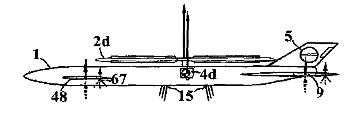
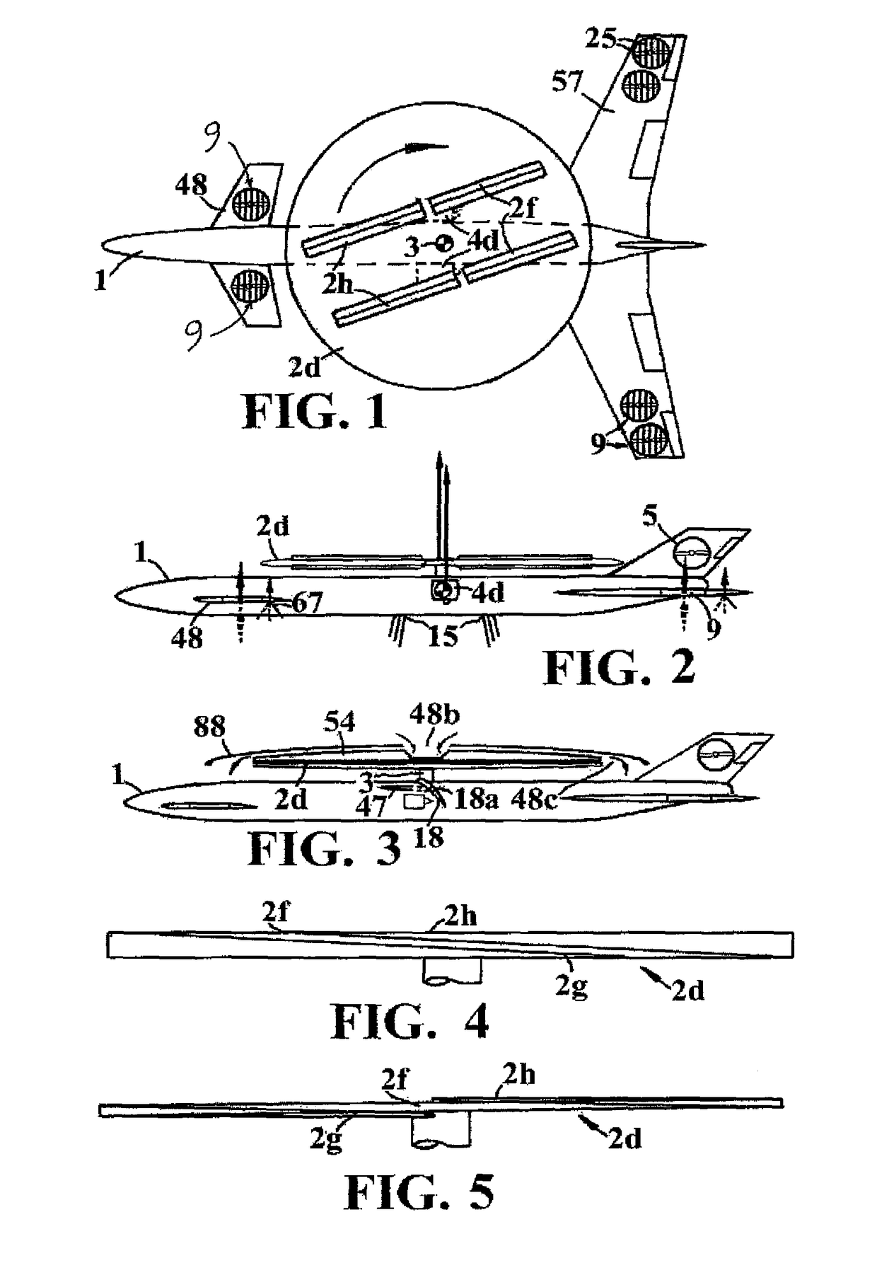
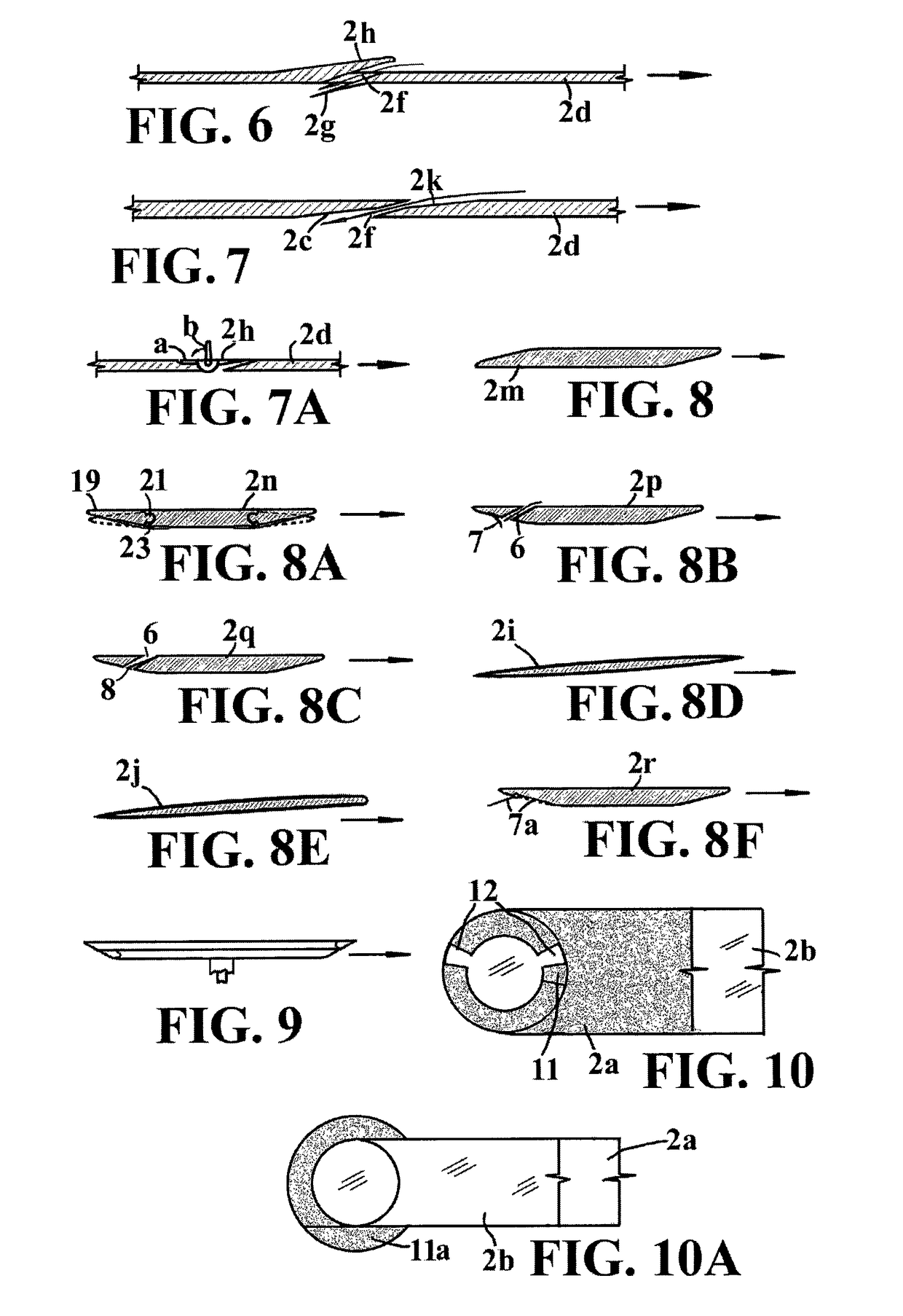
[0012]Lift propulsion and stabilizing system and procedure for vertical takeoff and landing aircraft that consists in applying simultaneously and combined as lifters during the initial portion of the climb and at the end of the descent of: a) some fans or electric turbines, EDF, driven by electric motors powered or driven by flywheels, compressed air stored in the frame tubular hollow structure of the aircraft or in air or nitrogen bottle, GPU, Group tire, APU, turbo-shaft, or generators or supergenerators, fuel cells or batteries and b) at least one rotor with external blades and / or wings rotating at medium or high speed, powered or driven by flywheels, compressed air stored in the frame of the hollow tubular structure of the aircraft or air or nitrogen bottle, GPU, Group tire, APU, turbo-shaft, generators or supergenerators, fuel cells and batteries, electric, pneumatic, hydraulic or mechanical, and / or c) the engine flow directed downwards and / or d) pressure air jets injected on l...


PUM


Abstract

Lift propulsion and stabilizing system and procedure for vertical takeoff and landing aircraft that consists in applying simultaneously and combined as lifters during the initial portion of the climb and at the end of the descent of: a) some fans or electric turbines, EDF, and b) at least one rotor with external blades and / or rotary and / or c) the engine flow directed downwards and / or d) pressure air jets injected on leading edges control fins, and / or e) water jets and / or f) supplemented with aerodynamic lift produced during frontal advance of the aircraft, the stabilization is achieved by the gyroscopic stiffness of the rotor and two or more lifting fans oscillating fins and / or air jets located on two or stabilizers more peripheral points in a plane perpendicular to the vertical axis of the aircraft.

Description

INDEX TO RELATED APPLICATIONS[0001]This application claims the benefit of PCT application PCT / ES2011 / 000147, filed Apr. 12, 2011, which claims the benefit of Spanish patent application numbers, P201100468 filed Apr. 11, 2011 and P201001236 filed Sep. 14, 2010, the disclosure of which are incorporated herein by reference in their entirety.FIELD OF THE INVENTION[0002]In systems for lift, propulsion and stabilization of manned and unmanned aircraft, radio control, firefighting, photography, carrier aircraft, supersonic, ultralights, gliders, etc.STATE OF THE ART[0003]The present invention can be considered a continuation of the patent ES-201000248. Aircraft have less lift at low speed, they need maximum power, large wings and flaps for the takeoff and landing, they are dangerous because of their high speed close to the ground, they use heavy landing gears, large airports, expensive runways and do not performs vertical takeoff. Helicopters are slow, expensive, heavy, complex and have li...

Claims


Application Information

Patent Timeline
Patent Type & Authority Patents(United States)
IPC IPC(8): B64C29/00B64C39/06B64C27/26F01D5/00B64D27/02B64D27/24B64C27/30B64D41/00
CPCF01D5/00B64C27/26B64C27/30B64C29/0025B64C29/0083B64C39/06B64D27/02B64D27/24B64D41/00B64D2027/026B64D2221/00Y02T50/62Y02T50/60
Inventor SAIZ, MANUEL M.
Owner SAIZ MANUEL M
Why Eureka
Try Eureka