
Arithmetic logic unit testing system and method

a logic unit and test system technology, applied in the field of arithmetic logic unit testing system and method, can solve the problems of large storage space needed for the expected result unit, difficult integration with other devices, large and more expensive expected result units, etc., and achieve the effect of less hardware overhead, short testing time and same or similar results

Active Publication Date: 2017-07-11
SHANGHAI XINHAO MICROELECTRONICS
View PDF11 Cites 0 Cited by
  • Summary
  • Abstract
  • Description
  • Claims
  • Application Information

AI Technical Summary

Benefits of technology

[0011]The disclosed systems and methods may provide fundamental solutions to the testing of arithmetic logic units in digital systems. Different from the conventional testing systems using a random vector generator, the disclosed systems and methods can provide the vectors according to the structure of the units, and may achieve the same or even better coverage than the covenantal ones within much shorter testing time. Further, the disclosed systems and methods may need much less hardware overhead comparing to the conventional testing systems using a ROM containing the vectors. Other advantages and applications are obvious to those skilled in the art.

Problems solved by technology

Therefore, a very large storage space is needed for the expected result unit.
This will certainly make the expected result unit larger and more expensive, and difficult to be integrated with other devices (including the arithmetic logic unit under testing, the main control equipment, etc.).
Therefore, the expected result unit cannot benefit from miniaturization and low cost from device integration.

Method used


Image

  • Arithmetic logic unit testing system and method
  • Arithmetic logic unit testing system and method
  • Arithmetic logic unit testing system and method

Examples


Embodiment Construction

Best Mode

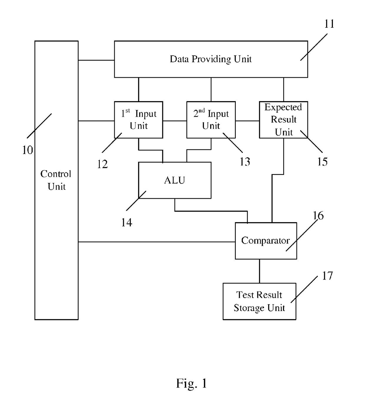
[0014]FIG. 1 illustrates an exemplary preferred embodiment(s).

MODE FOR THE INVENTION

Mode for Invention

[0015]Reference will now be made in detail to exemplary embodiments of the invention, which are illustrated in the accompanying drawings. The same reference numbers may be used throughout the drawings to refer to the same or like parts.

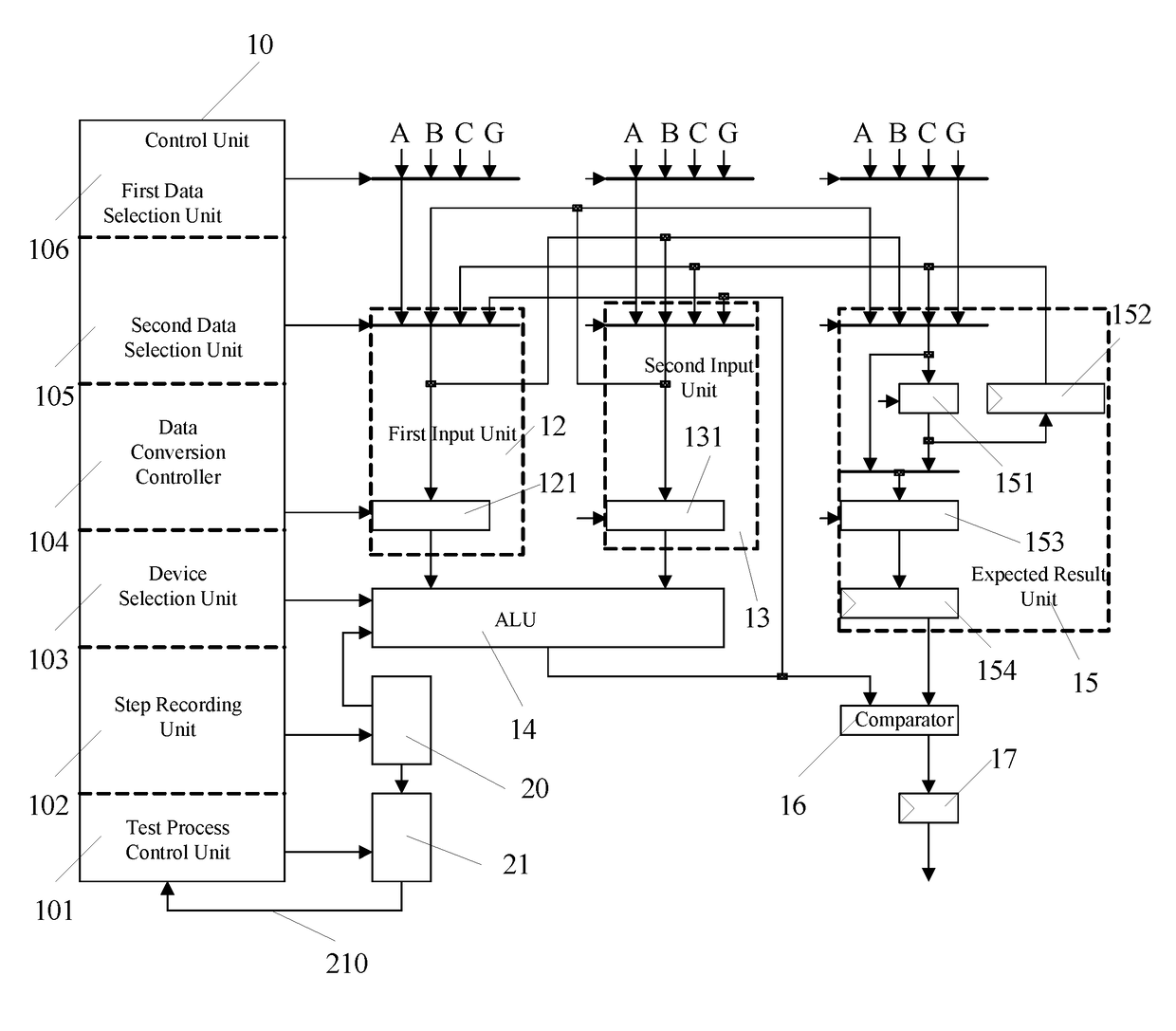
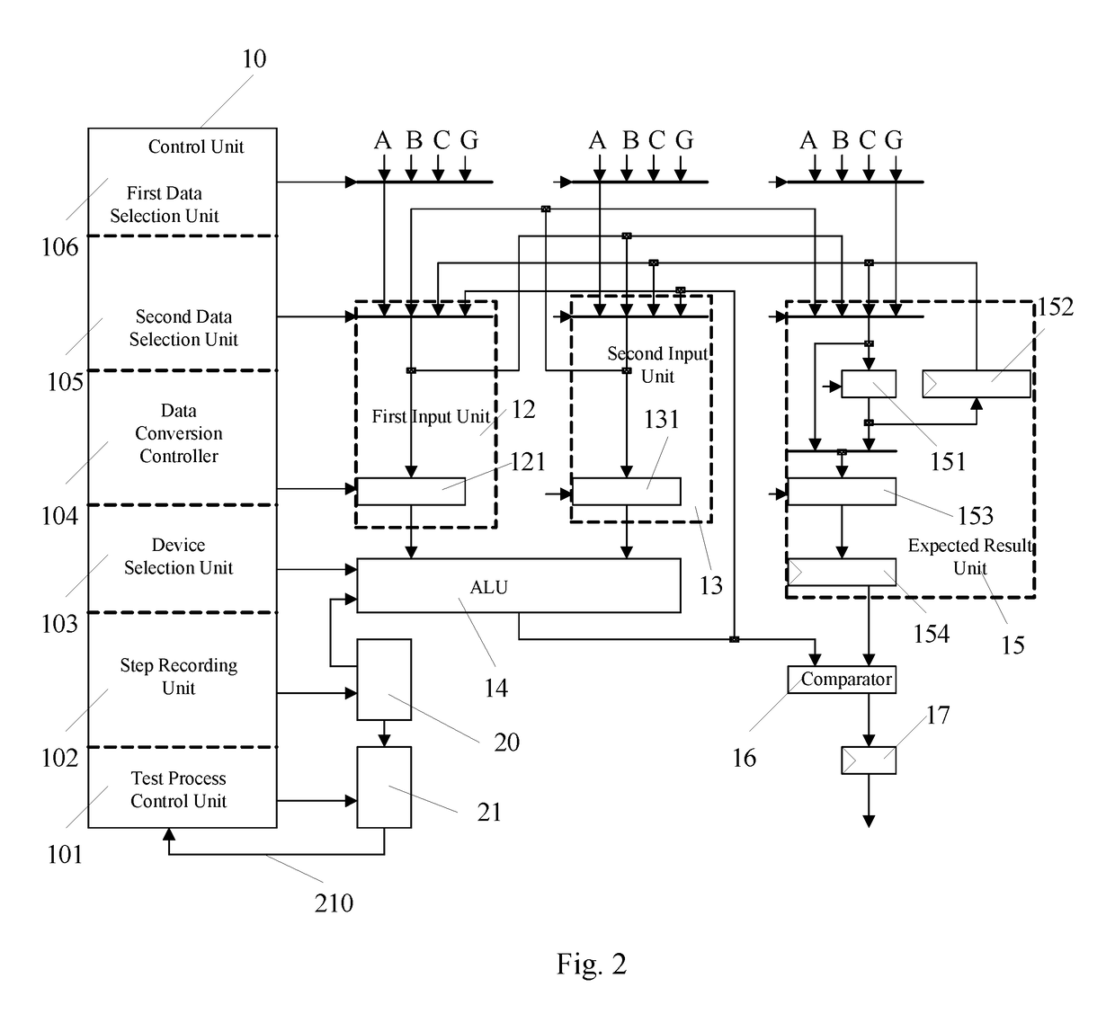
[0016]FIG. 1 shows a block diagram of a testing system for an arithmetic logic unit consistent with the disclosed embodiments. As shown in FIG. 1, the arithmetic logic unit testing system 1 includes a control unit 10, a data providing unit 11, a first input unit 12, a second input unit 13, an arithmetic logic unit 14, an expected result unit 15, a comparator 16, and a test result storage unit 17. Certain units may be omitted and other units may be added.

[0017]Various units may perform certain steps to complete a testing process of the arithmetic logic unit 14. For example, when performing the test, the control unit 10 may control testing proc...


PUM


Abstract

A testing system and method for an arithmetic logic unit are provided. The system includes: a control unit, a data providing unit, a first input unit, a second input unit, an arithmetic logic unit, an expected result unit, a comparator and a test result storage unit. The control unit controls the testing process. The data providing unit provides data for the first input unit, the second input unit and the expected result unit. The first input unit and the second input unit provide test data for the arithmetic logic unit. The arithmetic logic unit performs an operation and provides an operation result for the comparator. The expected result unit generates an expected result and provides the expected result of this round of testing for the comparator. The comparator compares the operation result with the expected result, and provides a comparison result for the test result storage unit.

Description

TECHNICAL FIELD[0001]The present invention generally relates to semiconductor device testing technologies and, more particularly, to a testing system and method for an arithmetic logic unit.BACKGROUND ART[0002]In product manufacturing process, product testing plays a vital role in enhancing product quality. Often, the product testing stage is required for many existing products. With technology development, an arithmetic logic unit is widely used to help accomplishing many kinds of repetitive and complex computational work, and to relieve people from such computational work, improving quality of life.[0003]In general, an arithmetic logic unit (ALU) includes an adder, a multiplier, a shifter, a logic operation unit and a memory. Currently, the arithmetic logic unit is often tested mainly by the following testing methods:[0004]The main control equipment in the testing process is controlled to provide input data for an arithmetic logic unit under testing and, at the same time, provides...

Claims


Application Information

Patent Timeline
Patent Type & Authority Patents(United States)
IPC IPC(8): G01R31/3177G01R31/3181G01R31/3183G01R31/317G06F11/22
CPCG01R31/3177G01R31/3183G01R31/31703G01R31/31713G01R31/31813G06F11/2226
Inventor LIN, CHENGHAO KENNETH
Owner SHANGHAI XINHAO MICROELECTRONICS
Learn More