
Ureteral stent and method for treating urological problems

a ureteral stent and ureteral stent technology, applied in the direction of stents, wound drains, etc., can solve the problems of oedema, irritation, pelvic congestion, and urine not being able to flow to the bladder and the kidney dilate, and the need for micturation is overwhelming in both men and women

Active Publication Date: 2017-07-18
VOGT BENOIT +2
View PDF13 Cites 0 Cited by
  • Summary
  • Abstract
  • Description
  • Claims
  • Application Information

AI Technical Summary

Benefits of technology

The patent describes a stent that can be used to treat ureteral obstruction. The stent has a small bladder end part that allows urine to drain into the bladder without causing discomfort. The stent also helps to dilate the meatus and ureter, making it easier to insert a ureteroscope or sheath. The stent reduces pain and prevents obstructions by allowing the ureter to drain around the threaded parts of the stent. The stent also reduces the risk of oedema by having a tapered shape.

Problems solved by technology

In cases of obstruction of the ureter, the urine no longer manages to flow to the bladder and the kidney dilates.
Firstly, after this stent is put in, the urine can not only flow freely from the kidney to the bladder, but also in the reverse direction from the bladder to the kidney, because the stent opens an anatomical system that normally prevents the urine from flowing back from the bladder to the kidney.
This abnormal reflux of urine to the kidney is unpleasant and painful.
Furthermore, due to its diameter this stent can rub inside the bladder or against the ureter, and give irritation, oedemas, pelvic congestion, or else an overwhelming need to micturate in both men and women.
For all these reasons, the stent is poorly tolerated by around 80% of patients.
For these reasons, the stent proposed by this document does not solve the problems described above because it still gives rise to irritation.

Method used


Image

  • Ureteral stent and method for treating urological problems
  • Ureteral stent and method for treating urological problems
  • Ureteral stent and method for treating urological problems

Examples


Embodiment Construction

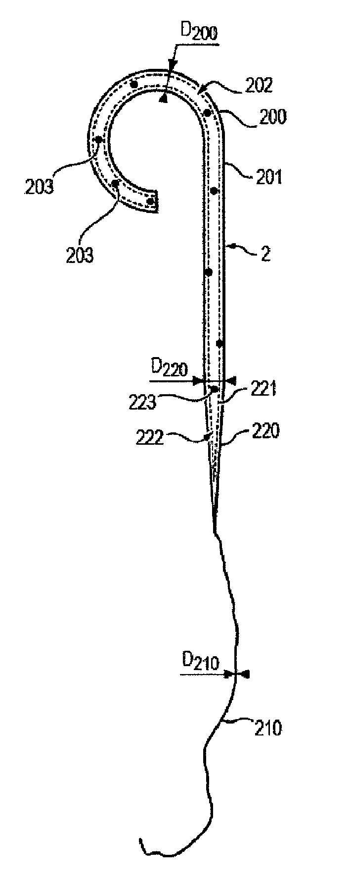
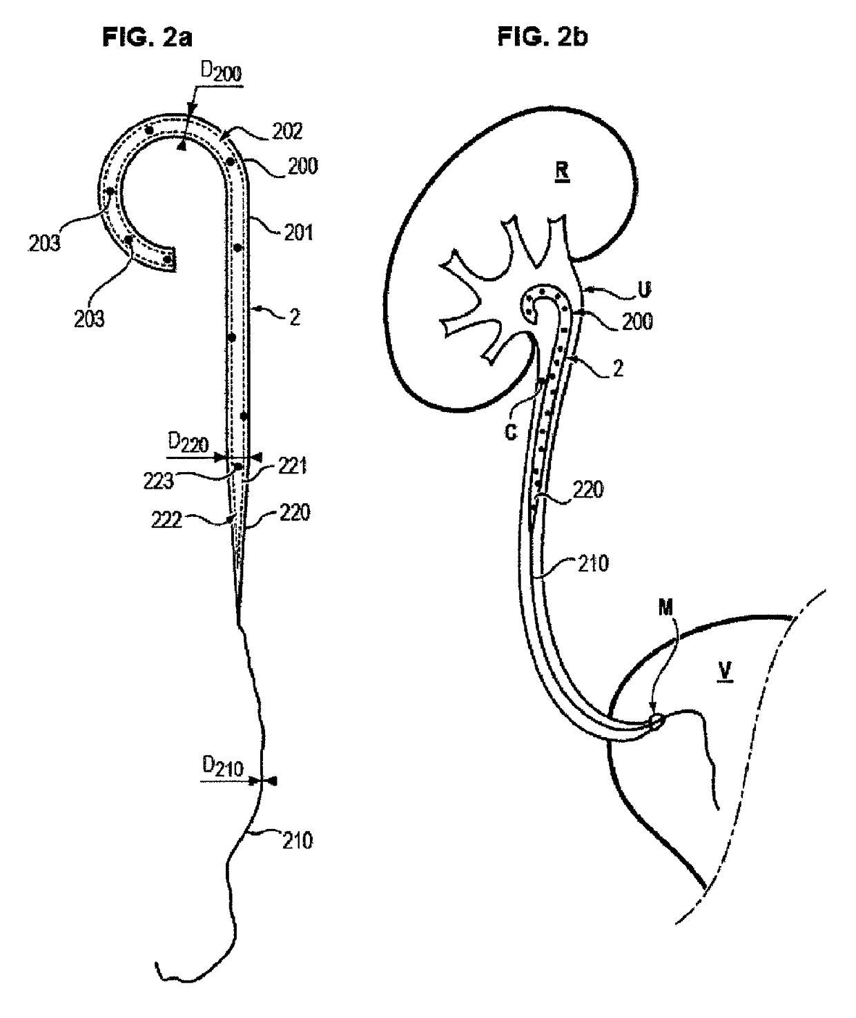
[0069]With reference to FIG. 2a, an embodiment of an endo-ureteral stent is represented.

[0070]This stent 2 includes a first kidney end part 200. This part is tubular, i.e. it comprises a cylindrical wall 201 delimiting an internal channel 202 wherein a fluid can circulate. A plurality of through holes 203 are further arranged in the cylindrical wall 201, allowing the fluid to enter into the internal channel 202 or exit it via the wall 201.

[0071]The kidney end part 200 is coiled into a J shape, i.e. it has a semi-circular or loop-shaped end (i.e. in the shape of a ring) allowing this part 200 to be held inside a kidney R once the stent is implanted.

[0072]Alternatively, this part can have one or more segments linked together by rounded bends to avoid any abrupt or cutting section.

[0073]With reference to FIG. 2b, the kidney end part 200 is configured to enter the kidney once the stent is in place, and extend from the kidney R to the ureter U of the patient. In this regard, it has a len...


PUM


Abstract

The proposed invention is a ureteral stent (2) comprising a kidney end part (200) and a bladder end part (210), the kidney end part (200) being tubular and curved, said stent (2) being characterized in that the bladder end part (210) has at least one thread, and in that the stent additionally comprises a tubular intermediate portion (220) extending between the kidney end part and the bladder end part, said portion having an external diameter decreasing towards the bladder end part, and the minimal external diameter of said portion (220), at the connection to the thread of the bladder end part (210), is substantially equal to the diameter of the thread, said portion having a length of between 0.5 cm and 12 cm.

Description

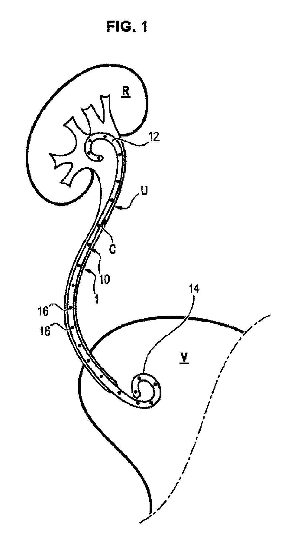
FIELD OF THE INVENTION[0001]The field of the invention is that of endo-ureteral stents, used for maintaining the flow of urine in the ureter.PRIOR ART[0002]With reference to FIG. 1, the ureter U is a channel connecting a kidney R to the bladder V, and wherein urine flows freely in the absence of obstacles.[0003]The ureter can become obstructed in some conditions, for example in the presence of kidney stones C, pyeloureteral junction syndromes, in cases of extrinsic compression by malignant or benign retroperitoneal fibrosis, in cases of ureteral or pyelic tumour, or again in cases of ischaemic or post-radiation ureteral stenosis.[0004]In cases of obstruction of the ureter, the urine no longer manages to flow to the bladder and the kidney dilates. An attack of renal colic then occurs.[0005]To remedy this obstruction, it is known to use a tubular endo-ureteral stent 1, having a median portion 10 placed in the ureter, this portion extending between two ends 12, 14.[0006]A first end 12 ...

Claims


Application Information

Patent Timeline
Patent Type & Authority Patents(United States)
IPC IPC(8): A61M27/00A61F2/82
CPCA61M27/008A61F2/82
Inventor VOGT, BENOITDESFEMMES, FRANCOIS-NOELDESGRIPPES, ARNAUD
Owner VOGT BENOIT
Learn More