
Hidden device with translating cover

a technology of hidden devices and covers, applied in the field of hidden devices, can solve the problems of restricting the field of view, and reducing the assembly efficiency of the assembly process, so as to achieve the effect of simplifying assembly

Active Publication Date: 2017-08-01
HUF NORTH AMERICA AUTOMOTIVE PARTS MFG
View PDF29 Cites 7 Cited by
  • Summary
  • Abstract
  • Description
  • Claims
  • Application Information

AI Technical Summary

Benefits of technology

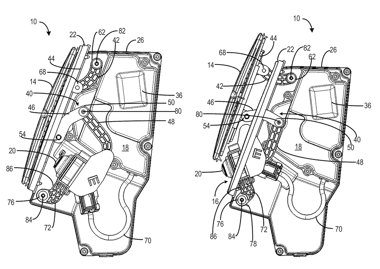
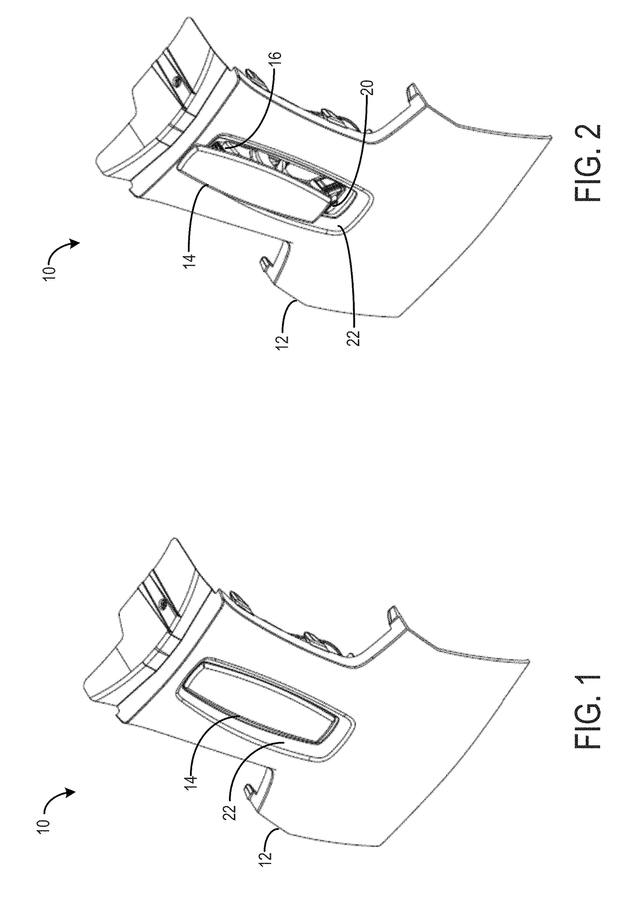
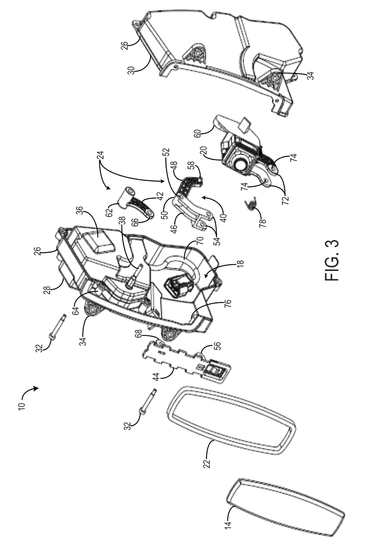
[0011]The disclosed system overcomes the aforementioned drawbacks by providing an assembly having a device, such as a camera or sensor which is hidden from normal view from the exterior of the motor vehicle, and a cover that can be translated between an open position and a closed position to expose the device. An emblem may be provided on the cover that is continually viewable while the cover is translated between the open and closed positions. The cover is attached to a linkage system that allows the cover to be translated adjacent to the mounting surface on the vehicle while simultaneously or sequentially deploying the device into a predetermined position that provides an unobstructed field of view. Due to the structure of the linkage assembly, this movement of the cover and the device can be achieved using a single power source or actuator.
[0017]According to some forms, the opening defined by the mounting surface may provide the device with an unobstructed field view when the translatable cover is in the second cover position (that is, the open position) and the device is in the second device position (that is, an extended position in which the device has been at least moved toward, if not partially through, the opening). The opening may be sized and shaped to facilitate centering the translatable cover while the translatable cover is in the first cover position to provide a water-tight seal between the cavity and the translatable cover. In another form, a ring-like gasket sized and shaped similar to the opening may be provided for additional sealing between the cavity and the translatable cover.
[0022]Additionally, the translatable cover and / or the plurality of linkages may incorporate a spring element, elastic member, or linkage delay that permits the power source (or the linkages) to be run or driven in some amount prior to actuation of the cover. This initial period of time in which the power source runs without encountering any mechanical resistance can help to avoid overloading of the power source in the event that significant resistance is met as might be the case, for example, if the cover and mounting surface have some ice, mud or other type of restrictive element collected thereon. Thus, by permitting the power source to have some amount of lead in or run length before encountering resistance, it is more likely to be able to overcome this resistance than if the resistance was encountered upon initial running of the power source.

Problems solved by technology

However, uncovered cameras and sensors are prone to dirt exposure, stone chipping and theft.
While a pivoting cover may accommodate a simple uncovering of the device, in many instances the cover may cause the cover ornamentation, such as a manufacturer logo, to be obstructed from viewing in the open state and may still restrict the field of view.
However, achieving this certainly complicates the assembly as there are now two items that are separately driven and this frequently requires two actuators: one to actuate the cover and another to actuate the device.
Further, introducing a movable camera or sensor creates an entirely new set of potential problems as the position of a camera or sensor can be highly sensitive; that is, even small mechanical adjustments can result in significant changes in the viewing area.
In assemblies with movable components, as the components are repeatedly moved from a retracted position to a deployed position and back again, the various assembly components may wear or small changes to the components such as the actuator may occur and may cause the range of motion to increase or decrease overtime.
Additionally, even small vibrations or other sudden outside forces (from, for example, backing a vehicle up) might jar the camera or sensor in a way that causes the position of the camera to shift.
Thus, reliably and repeatedly driving the device to a specific position that captures the desired field of view or location surrounding the vehicle is problematic in current systems.
This problem is only exacerbated in systems in which multiple camera field of view amalgamation is required.

Method used


Image

  • Hidden device with translating cover
  • Hidden device with translating cover
  • Hidden device with translating cover

Examples


Embodiment Construction

[0033]Before any embodiments of the invention are explained in detail, it is to be understood that the invention is not limited in its application to the details of construction and the arrangement of components set forth in the following description or illustrated in the following drawings. The invention is capable of other embodiments and of being practiced or of being carried out in various ways. Also, it is to be understood that the phraseology and terminology used herein is for the purpose of description and should not be regarded as limiting. The use of “including,”“comprising,” or “having” and variations thereof herein is meant to encompass the items listed thereafter and equivalents thereof as well as additional items. Unless specified or limited otherwise, the terms “mounted,”“connected,”“supported,” and “coupled” and variations thereof are used broadly and encompass both direct and indirect mountings, connections, supports, and couplings. Further, “connected” and “coupled”...


PUM


Abstract

An assembly for deploying a device from a cavity. The assembly includes a translatable cover and a mounting surface defining an opening sized to receive the translatable cover thereover. The device is received in the cavity beneath the mounting surface and is actuatable between a first device position and a second device position. A plurality of linkages are positioned within the cavity. At least one of the plurality of linkages is coupled to a power source for actuating the plurality of linkages and at least one of the plurality of linkages is coupled to the translatable cover and to the device. Thus, when the power source actuates the plurality of linkages, the translatable cover is translated relative to the mounting surface from a first cover position to a second cover position and the device is actuated from the first device position to the second device position.

Description

CROSS-REFERENCE TO RELATED APPLICATION[0001]Not applicable.STATEMENT OF FEDERALLY SPONSORED RESEARCH OR DEVELOPMENT[0002]Not applicable.BACKGROUND[0003]This disclosure relates to devices, such as cameras and sensors, used in motor vehicles. In particular, this disclosure relates to devices that are deployable with the movement of a cover using a linkage assembly.[0004]Many motor vehicles now come equipped with some variation of a camera and sensor system to provide real-time monitoring or viewing of an area near the motor vehicle. For example, cameras, sensors, or both are often positioned on the front of the vehicle or on the rear of the motor vehicle. The cameras and sensors can detect the areas surrounding the car that are not otherwise viewable with the conventional mirrors. Such cameras and sensors can be used to assist the vehicle operator in parking or maneuvering the vehicle during normal operation, although they are certainly not limited to this specific use.[0005]To provid...

Claims


Application Information

Patent Timeline
Patent Type & Authority Patents(United States)
IPC IPC(8): B60R11/04B60R11/00
CPCB60R11/04B60R2011/004B60R2011/0094
Inventor DA DEPPO, LYNN D.KAMAL, EHABBAUER, STEVECARSON, DOUGLASNEWKIRK, DAVID
Owner HUF NORTH AMERICA AUTOMOTIVE PARTS MFG
Learn More