Light emitting device and adaptive driving beam headlamp system

a technology of light emitting devices and headlamp systems, which is applied in the direction of sustainable manufacturing/processing, final product manufacturing, lighting and heating apparatus, etc., can solve the problems of obstructing the miniaturization of the light emitting device, requiring a complex manufacturing process and higher manufacturing cost, and increasing the size of the substra

Active Publication Date: 2017-08-01
NICHIA CORP
View PDF31 Cites 22 Cited by
  • Summary
  • Abstract
  • Description
  • Claims
  • Application Information

AI Technical Summary

Benefits of technology

[0012]The present disclosure can provide a light emitting device with which a smaller size is achieved with a simple structure, and individual turning on and off is possible while achieving sufficient performance of the light emitting elements.
[0013]Furthermore, this light emitting device can be used to provide a high-performance adaptive driving beam headlamp system.

Problems solved by technology

However, in the case of forming a matrix wiring on a substrate, particularly in order to individually turn on and off each of a plurality of light emitting elements, usually, a multilayer wiring is required, resulting in a complicated configuration, which requires complex manufacturing process and higher manufacturing costs.
Also, this results in an increase in the size of the substrate, obstructing the miniaturization of the light emitting device.
However, with a light source in which high-density mounting is required in order to achieve high brightness, such as with an automotive light source, the width, pitch, and so forth of the wiring pattern need to be microminiaturized, and a decrease in the dimensional accuracy of a wiring pattern caused by shrinkage accompanying the firing of a ceramic makes it difficult to design the wiring of a matrix board.

Method used


Image

  • Light emitting device and adaptive driving beam headlamp system
  • Light emitting device and adaptive driving beam headlamp system
  • Light emitting device and adaptive driving beam headlamp system

Examples


embodiment 1

Drive Substrate

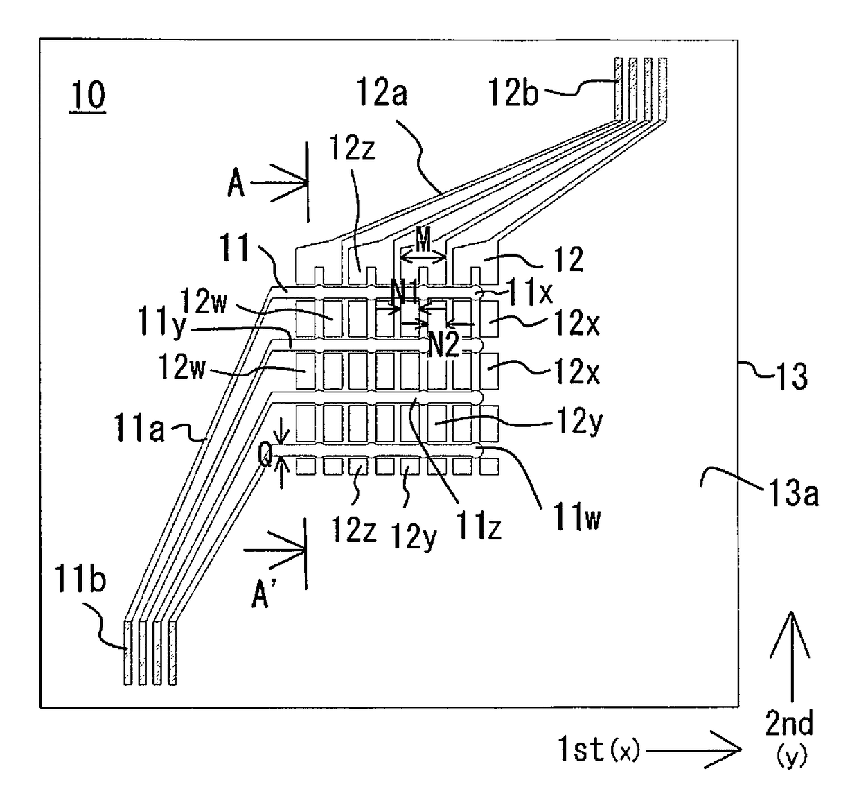
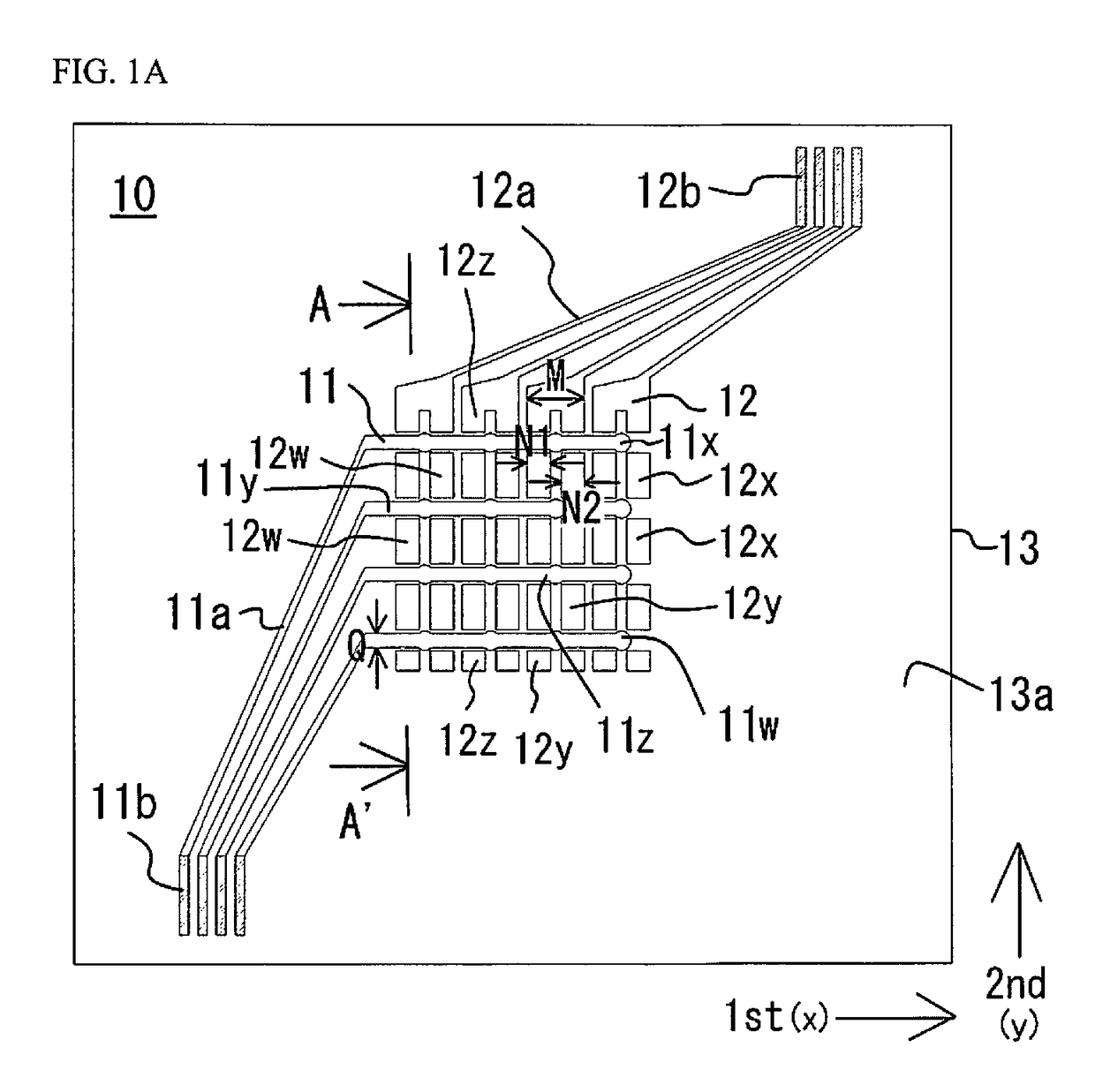
[0100]As shown in FIG. 1A, a drive substrate 10 used by a light emitting device 90 in this embodiment has a substrate 13, first wiring 11 (examples of first wiring members), and second wiring 12 (examples of second wiring members).

[0101]The substrate 13 is constituted by a single-layer structure made of aluminum nitride. Its size is 10×10 mm and its thickness is 0.5 mm, for example.

[0102]The first wiring 11 and the second wiring 12 are formed by a TiW / Cu / Ni / Au stacked-layer structure (starting from the substrate 13 side) on a first main surface 13a of the substrate 13. The TiW and copper films are each formed in a thickness of 0.1 μm by sputtering through a mask on the substrate 13, and the nickel and gold films are formed on the surface thereof by plating in a thickness of 1.27 μm and 1.5 μm, respectively.

[0103]When the first main surface 13a of the substrate 13 will be the xy plane, for example, there are four first wiring 11 disposed extending in the x axis directi...

modification example 1

Drive Substrate

[0128]As shown in FIG. 3A, the drive substrate 20 in this modification example has the substrate 13, first wiring 21, and second wiring 22. The first wiring 21 and the second wiring 22 are disposed extending in the x axis direction and the y axis direction, respectively, so that the light emitting elements are disposed in a 3×3 matrix.

[0129]The first wiring 21 is disposed extending in three parallel rows in the x axis direction, as indicated by the first wiring 21x, 21y, and 21z.

[0130]The second wiring 22 is disposed in a number corresponding to three rows so as to pair up with the three rows of first wiring 21 along the y axis direction, as indicated by the second wiring 22x, 22y, and 22z. However, the second wiring 22x, 22y, and 22z disposed along the y axis direction are disposed with two between the first wirings 21, one at the distal end of the first wiring 21, and one at the other end, with the four of them separated from one another.

[0131]The width M of the se...

embodiment 2

Drive Substrate

[0135]As shown in FIG. 4A, the drive substrate 30 in this embodiment has the substrate 13, first wiring 31, and second wiring 32. The first wiring 31 and the second wiring 32 are disposed in the x axis direction and the y axis direction, respectively, so that the light emitting elements are disposed in a 3×3 matrix.

[0136]The first wiring 31 is disposed extending in three rows in the x axis direction. However, one row of the first wiring 31 is branched into three.

[0137]The second wiring 32 is disposed in a number corresponding to three rows so as to pair up with the three rows of first wiring 31 along the y axis direction, as indicated by the second wiring 32x, 32y, and 32z. However, the second wiring 32x, 32y, and 32z disposed along the y axis direction are disposed with two between the first wirings 31, one at the distal end of the first wiring 31, and one at the other end, with the four of them separated from one another.

[0138]Otherwise, the configuration is substan...


PUM


Abstract

A light emitting device includes a substrate, a plurality of first wiring members, a plurality of second wiring members and a plurality of light emitting elements. The first wiring members extend in a first direction. The second wiring members extend in a second direction. Each of the second wiring members is segmented into a plurality of second wiring portions. The light emitting elements are disposed along the second direction. A first electrode of the light emitting element is connected to a corresponding one of the first wiring members. A second electrode of the light emitting element has a first connection part and a second connection part that is linked to the first connection part. The first connection part and the second connection part are connected to a corresponding one of the second wiring members and bridge at least two of the segmented second wiring portions in the second direction.

Description

CROSS-REFERENCE TO RELATED APPLICATIONS[0001]This application claims priority to Japanese Patent Application No. 2014-222249 filed on Oct. 31, 2014, and No. 2015-187821 filed on Sep. 25, 2015. The entire disclosures of Japanese Patent Application No. 2014-222249 and No. 2015-187821 are hereby incorporated herein by reference.BACKGROUND[0002]1. Technical Field[0003]The present disclosure relates to a light emitting device and to an adaptive driving beam headlamp system.[0004]2. Description of Related Art[0005]With a light emitting device featuring light emitting diodes (LEDs) or other such light emitting elements, a plurality of light emitting elements are mounted on an insulated substrate on which matrix wiring has been formed. As a result, high brightness is obtained, and such devices have been utilized as automotive light sources and the like in recent years.[0006]However, in the case of forming a matrix wiring on a substrate, particularly in order to individually turn on and off ...

Claims


Application Information

Patent Timeline
Patent Type & Authority Patents(United States)
IPC IPC(8): H01L33/62B60Q1/16H01L33/54B60Q1/14H01L33/08F21S8/10H01L25/075H05K1/11H01L33/10H01L33/38H05K1/02F21Y105/10F21Y105/12
CPCH01L33/62B60Q1/1423B60Q1/16F21S48/1154F21S48/1195F21S48/1747H01L25/0753H01L33/08H01L33/10H01L33/54H05K1/111B60Q2300/42B60Q2300/45F21Y2105/10F21Y2105/12H01L33/38H01L2224/16225H01L2924/0002H01L2924/181H01L2924/18161H05K1/0287H05K2201/09663H05K2201/10106Y02P70/611H01L2924/00012H01L2924/00B60Q1/143F21S41/153F21S41/18F21S41/663Y02P70/50
Inventor NAKABAYASHI, TAKUYA
Owner NICHIA CORP
Why Eureka
Try Eureka