Capacitive touch panel with balanced parallel driving

a capacitive touch panel and parallel driving technology, applied in the field of capacitive touch panel devices, can solve the problems of reducing the dynamic range of the sensor, affecting the performance of the touch panel, and unable to detect multiple simultaneous touch input events, so as to maximize the dynamic range and improve the signal-to-noise ratio.

Active Publication Date: 2017-08-08
SHARP KK
View PDF12 Cites 3 Cited by
  • Summary
  • Abstract
  • Description
  • Claims
  • Application Information

AI Technical Summary

Benefits of technology

[0011]A method in accordance with the present invention enables measurement of capacitance in a capacitive touch panel with improved signal-to-noise ratio (SNR) and maximized dynamic range. The capacitive touch panel includes an array of electrode elements with each electrode element including at least one drive electrode and one sense electrode. Mutual coupling capacitors are formed between the drive electrode and sense electrode in each electrode element. The capacitance of the mutual coupling capacitors may change due to the presence of an input object in close proximity to the surface of the touch panel. The input object may be, for example, a finger or a pen, or a stylus or the like. The capacitance of a mutual coupling capacitor without the presence of an input object, known as the baseline capacitance, may be significantly larger than the change in capacitance caused by the input object.
[0015]According to one embodiment, a capacitive touch sensor includes: an array of electrode elements, each electrode element including a drive electrode and a sense electrode, the drive electrode and the sense electrode forming at least one mutual coupling capacitor in each electrode element; and a controller operatively coupled to the array of electrode elements, the controller configured to provide excitation signals to the array of electrode elements over at least one measurement period, and to measure the at least one mutual coupling capacitance over the at least one measurement period, wherein the excitation signals applied during the at least one measurement period are balanced to reduce the effect of baseline capacitance.

Problems solved by technology

Although simple in construction and operation, surface capacitive type touch panels are unable to detect multiple simultaneous touch input events as occurs when, for example, two or more fingers are in contact with the touch panel.
A limitation of this method, however, is that the current measurement means 24 may saturate whilst making the capacitance measurements.
As a result, the dynamic range of the sensor may be reduced and the performance of the touch panel may be degraded.
However, since the length of an M-sequence is limited to values that are equal to 2n−1, where n is an integer number, this method is not suitable for touch panels where the number of drive electrodes is not equal to 2n−1.
The signal-to-noise ratio and dynamic range requirements of such a system may however be more stringent that conventional applications.

Method used


Image

  • Capacitive touch panel with balanced parallel driving
  • Capacitive touch panel with balanced parallel driving
  • Capacitive touch panel with balanced parallel driving

Examples


second embodiment

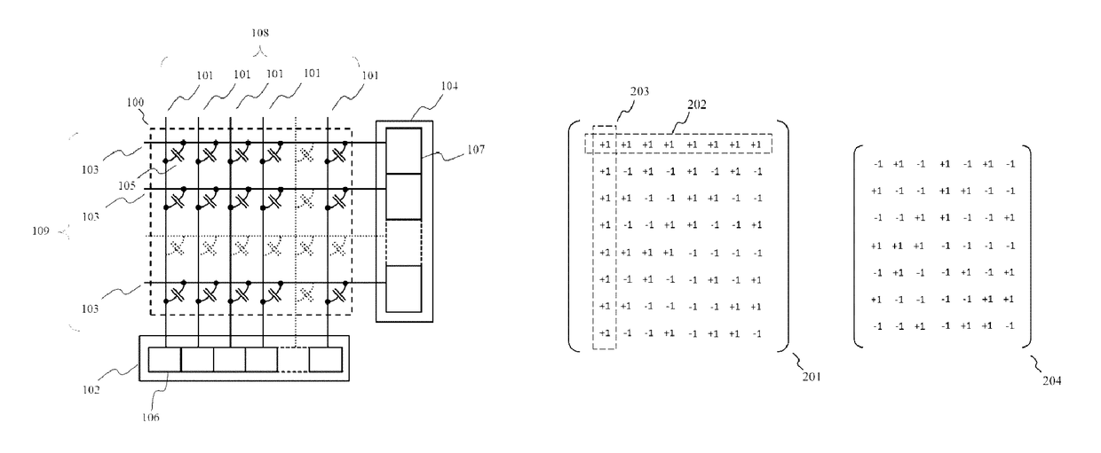
[0153]In accordance with the invention, a method is provided to create a drive matrix suitable for measuring with high dynamic range the capacitances of an electrode array with more than one drive electrode in each electrode element. An exemplary arrangement of electrode array in accordance with the present embodiment is shown schematically in FIG. 10A. An exemplary arrangement of an electrode element in accordance with the present embodiment is shown in FIG. 10B. The electrode element includes a pair of drive electrodes 601 and a sense electrode 604. Different parts of the same drive electrode may be connected by connecting wires 613, 614 and contact holes 612. Each drive electrode pair 601 includes a first drive electrode, drive electrode A 602, and a second drive electrode, drive electrode B 603. As shown in FIG. 10B, the two electrodes 602, 603 are arranged symmetrically around each drive electrode such that the first drive electrodes is adjacent to the sense electrode whilst th...

first embodiment

[0162]To meet these requirements the drive matrix D3 of the present embodiment may, for example, be constructed by applying a well-known Sylvester type construction method using a primary drive matrix D of dimension N×N as illustrated in FIG. 12. The primary drive matrix D may be constructed using the method described previously for this invention.

[0163]It is well-known that the signal-to-noise ratio of a touch panel may be improved by using a differential sensor circuit to measure the current generated on the sense electrodes. A suitable differential sensor circuit is disclosed, for example, in International Patent Application PCT / JP2012 / 006680 filed on 18 Oct. 2012. Further it is known that more than one sense electrode may be provided in each electrode element for the purposes of improving SNR or measuring the height of the input object above the touch panel surface. For example, FIG. 13 shows a known arrangement of an electrode element that comprises a sense electrode pair 701 a...

fourth embodiment

[0164]In accordance with the invention, a method is provided for measuring with high dynamic range and maximum achievable signal-to-noise ratio the capacitances of an electrode array with more than one sense electrode in each electrode element. As shown in FIG. 14, an array of electrode elements 100 including a set of drive electrodes 108 and sense electrode pairs 701 may be connected to a sense unit 800 which includes a differential sensing apparatus. The differential sensing apparatus may include first multiplexer circuits 810, second multiplexer circuits 820 and differential sensing circuits 830. The sense electrodes may be connected to the sense unit as illustrated such that the first sense electrodes 702 are connected to the first multiplexing circuits 810 and the second sense electrodes 703 are connected to the second multiplexing circuits 820.

[0165]Although the invention has been shown and described with respect to a certain embodiment or embodiments, equivalent alterations a...


PUM


Abstract

A capacitive touch sensor includes an array of electrode elements, each electrode element including a drive electrode and a sense electrode, the drive electrode and the sense electrode forming at least one mutual coupling capacitor in each electrode element. A controller is operatively coupled to the array of electrode elements, the controller configured to measure the at least one mutual coupling capacitance over at least one measurement period. In addition, excitation signals applied during the at least one measurement period are balanced to reduce the effect of baseline capacitance.

Description

TECHNICAL FIELD AND APPLICATIONS OF THE INVENTION[0001]The present invention relates to touch panel devices. In particular, this invention relates to capacitive type touch panels. Such a capacitive type touch panel device may find application in a range of consumer electronic products including, for example, mobile phones, tablet and desktop PCs, electronic book readers and digital signage products.BACKGROUND ART[0002]Touch panels have recently become widely adopted as the input device for high-end portable electronic products such as smart-phones and tablet devices. Although, a number of different technologies can be used to create these touch panels, capacitive systems have proven to be the most popular due to their accuracy, durability and ability to detect touch input events with little or no activation force.[0003]The most basic method of capacitive sensing for touch panels is the surface capacitive method—also known as self-capacitance—for example as disclosed in U.S. Pat. No....

Claims


Application Information

Patent Timeline
Patent Type & Authority Patents(United States)
IPC IPC(8): G06F3/044
CPCG06F3/044G06F3/0418G06F3/0445G06F3/0446G06F3/04166
Inventor SLAMKUL, DAURENBROWN, CHRISTOPHER JAMESKAY, ANDREW
Owner SHARP KK
Why Eureka
Try Eureka