
System and method of estimating values for commands to cause vehicles to follow a trajectory in a complex track network

a technology of complex track network and command, applied in the direction of railway signalling, vehicle signalling indicator, railway signalling, etc., can solve the problems of limiting the convenience of users, difficult for all but the largest and/or most affluent communities and cities to justify and/or afford the cost of new construction, and high cost, etc., to achieve convenient justified, reduce the cost of net present cost, and improve the effect of cost benefit ratio

Active Publication Date: 2017-08-15
CYBERTRAN INT
View PDF12 Cites 1 Cited by
  • Summary
  • Abstract
  • Description
  • Claims
  • Application Information

AI Technical Summary

Benefits of technology

The present invention is a ground transportation system that is cost-effective and suitable for lower density areas. It can also carry a large number of passengers, making it useful for high-density areas. The system has a higher degree of precision and coordination compared to conventional systems. It uses a control system that enforces vehicle movement along a specific route and adjusts its position and velocity to reduce errors. The invention also includes a method for estimating the force needed to achieve a given target velocity and acceleration.

Problems solved by technology

They are, however, very expensive.
A typical, but conservative order of magnitude system capital cost for a system is approximately $100 million per bi-directional track mile of system, making it difficult for all but the largest and / or most affluent communities and cities to justify and / or afford the cost of new construction.
This limitation has the effect of constraining the reach of these systems, and thus limiting the convenience to the users who can only ride the systems to the few locations to which guideway has been constructed.
The high cost of systems requires a high ridership to justify the cost.
However, high guideway costs limit construction and thus the reach of fixed guideway systems.
This limits convenience to the riders, making it difficult to achieve the high ridership needed to justify the high cost.
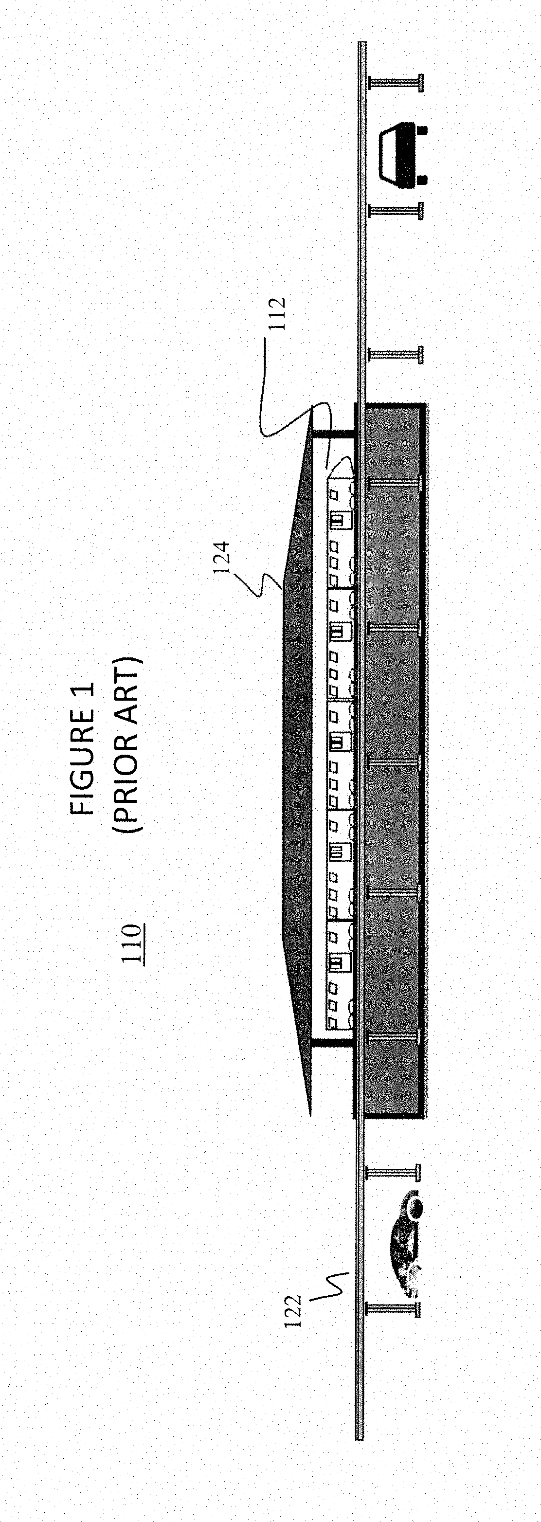
This, however, requires very costly guideway 122 and station structures 124, 126, which limits the system's reach and thus convenience for the users, especially for those who want to travel to the generally more widely distributed retail, residential, or recreational destinations.
With guideway 122 and station structures 124, 126 that must be built to handle long heavy trains 112 to support demand during commute hours, the result is an expensive but marginally justifiable solution for commute hour travel which is far too expensive to justify for other periods of the day and other destinations.
Given the limited speed and capacity of these systems, even with the somewhat lower cost of construction due to the use of smaller vehicles, the benefit per cost is still poor.
Furthermore, with the lower speeds and line capacities, these systems are limited in utility to local service routes.
However, with the very small cars, high speeds are difficult to achieve and line capacities are severely restricted.
With rubber-tired vehicles, however, the top speed of the system is 30 mph thus limiting its applicability to low speed local service lines.
However, certain challenges remain.
This cannot be achieved with current systems.
Relatedly, since a collision between two vehicles is a life-threatening event, control functions that prevent collisions are critical to safety.

Method used


Image

  • System and method of estimating values for commands to cause vehicles to follow a trajectory in a complex track network
  • System and method of estimating values for commands to cause vehicles to follow a trajectory in a complex track network
  • System and method of estimating values for commands to cause vehicles to follow a trajectory in a complex track network

Examples


Embodiment Construction

[0022]The present invention will now be described in detail with reference to the drawings, which are provided as illustrative examples of the invention so as to enable those skilled in the art to practice the invention. Notably, the figures and examples below are not meant to limit the scope of the present invention to a single embodiment, but other embodiments are possible by way of interchange of some or all of the described or illustrated elements. Moreover, where certain elements of the present invention can be partially or fully implemented using known components, only those portions of such known components that are necessary for an understanding of the present invention will be described, and detailed descriptions of other portions of such known components will be omitted so as not to obscure the invention. Embodiments described as being implemented in software should not be limited thereto, but can include embodiments implemented in hardware, or combinations of software and...


PUM


Abstract

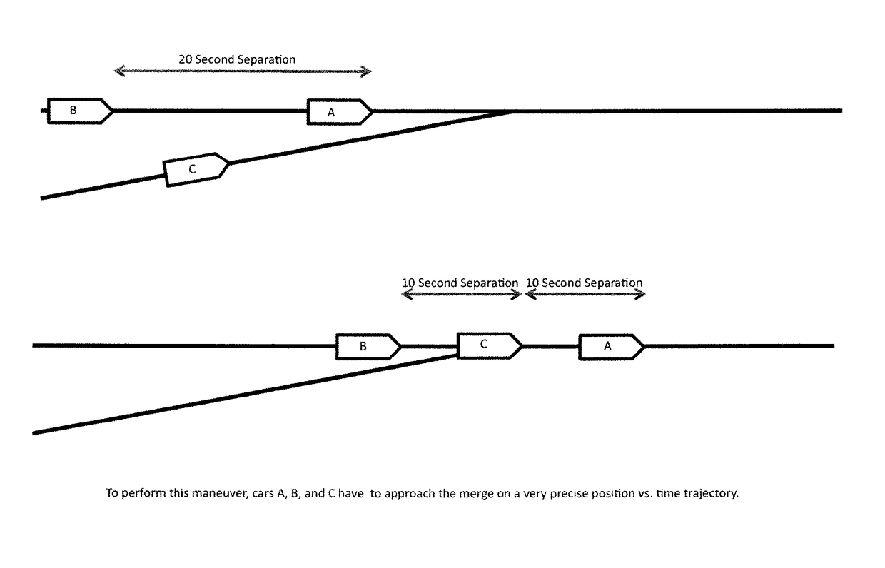
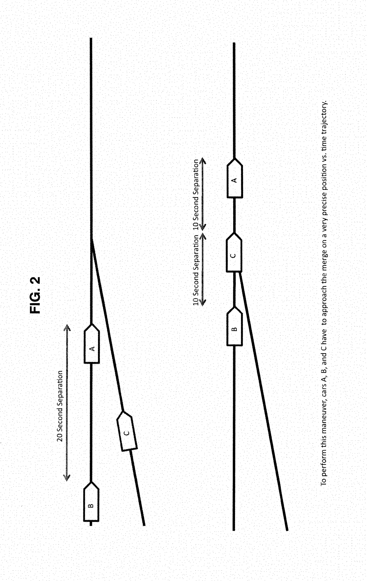
The invention relates to systems and methods that provide a higher degree of precision and a greater coordination of vehicle movement than is possible in conventional systems. A control system is designed to enforce vehicle movement along a route to a position versus time trajectory. The control system includes control equipment on the vehicle that reports its location on the track periodically. The controlling computer receives the report, and knowing where the vehicle should be and how fast it should be traveling at that point in time via a run definition table prepared for the route, calculates a position and velocity error, then calculates and sends a tractive effort adjustment command to the vehicle that attempts to reduce the position and velocity error. The invention includes a method for providing an estimated force command for a given target velocity and acceleration that can be used in the overall control methodology.

Description

CROSS-REFERENCE TO RELATED APPLICATIONS[0001]The present application is a continuation-in-part of U.S. patent application Ser. No. 13 / 218,422, filed Aug. 25, 2011. The present application is also a continuation-in-part of U.S. patent application Ser. No. 13 / 218,423, filed Aug. 25, 2011. The present application is also a continuation-in-part of U.S. patent application Ser. No. 13 / 218,429, filed Aug. 25, 2011. The present application is also a continuation-in-part of U.S. patent application Ser. No. 13 / 218,434, filed Aug. 25, 2011. The present application also claims priority to U.S. Provisional Application No. 61 / 459,247, filed Dec. 10, 2010. The contents of all such applications are incorporated herein by reference in their entirety.FIELD OF THE INVENTION[0002]The present invention relates to fixed guideway transportation systems, and more particularly to developing vehicle commands that can be used to cause the vehicle to follow a desired trajectory in a fixed guideway system.BACKG...

Claims


Application Information

Patent Timeline
Patent Type & Authority Patents(United States)
IPC IPC(8): B61L25/00B61L3/00B60W50/00
CPCB61L25/00B60W50/00B61L3/00B61L15/0072B61L25/025B61L15/0058B61L15/0062
Inventor NISHINAGA, EUGENE IWAONISHINAGA, KEVIN KOHEILEE, MARK
Owner CYBERTRAN INT
Learn More