Inductive displacement sensor with a measuring head comprising a passive resonant circuit

a passive resonant circuit and inductive displacement technology, applied in the direction of coils, electrical/magnetic measuring arrangements, using electrical/magnetic means, etc., can solve problems such as inability to measure values, and achieve the best possible cost-benefit ratio

Active Publication Date: 2005-09-13
BALLUFF
View PDF4 Cites 10 Cited by
  • Summary
  • Abstract
  • Description
  • Claims
  • Application Information

AI Technical Summary

Benefits of technology

[0012]Now, it is the object of the present invention to improve a displacement sensor of the before-mentioned kind so that the disadvantages discussed above, especially the before-mentioned air coupling effects, can be avoided as efficiently as possible and with the best possible cost-benefit ratio.

Problems solved by technology

Now, it is a disadvantage of the displacement sensor described in DE 39 13 861 A1 and DE 100 16 540.0 that the measuring head is of the active type so that, consequently, it requires a permanent energy supply which can be realized only by lines that move together with the head.
The measuring arrangement described in FR 2 682 760 A1 is connected with the disadvantage that temperature influences and positional variations of the displacement sensor may lead to unstable measured values.
In addition, the displacement sensors known from the prior art are, on principle, connected with the problem known as the “air coupling” phenomenon.

Method used


Image

  • Inductive displacement sensor with a measuring head comprising a passive resonant circuit
  • Inductive displacement sensor with a measuring head comprising a passive resonant circuit
  • Inductive displacement sensor with a measuring head comprising a passive resonant circuit

Examples


Embodiment Construction

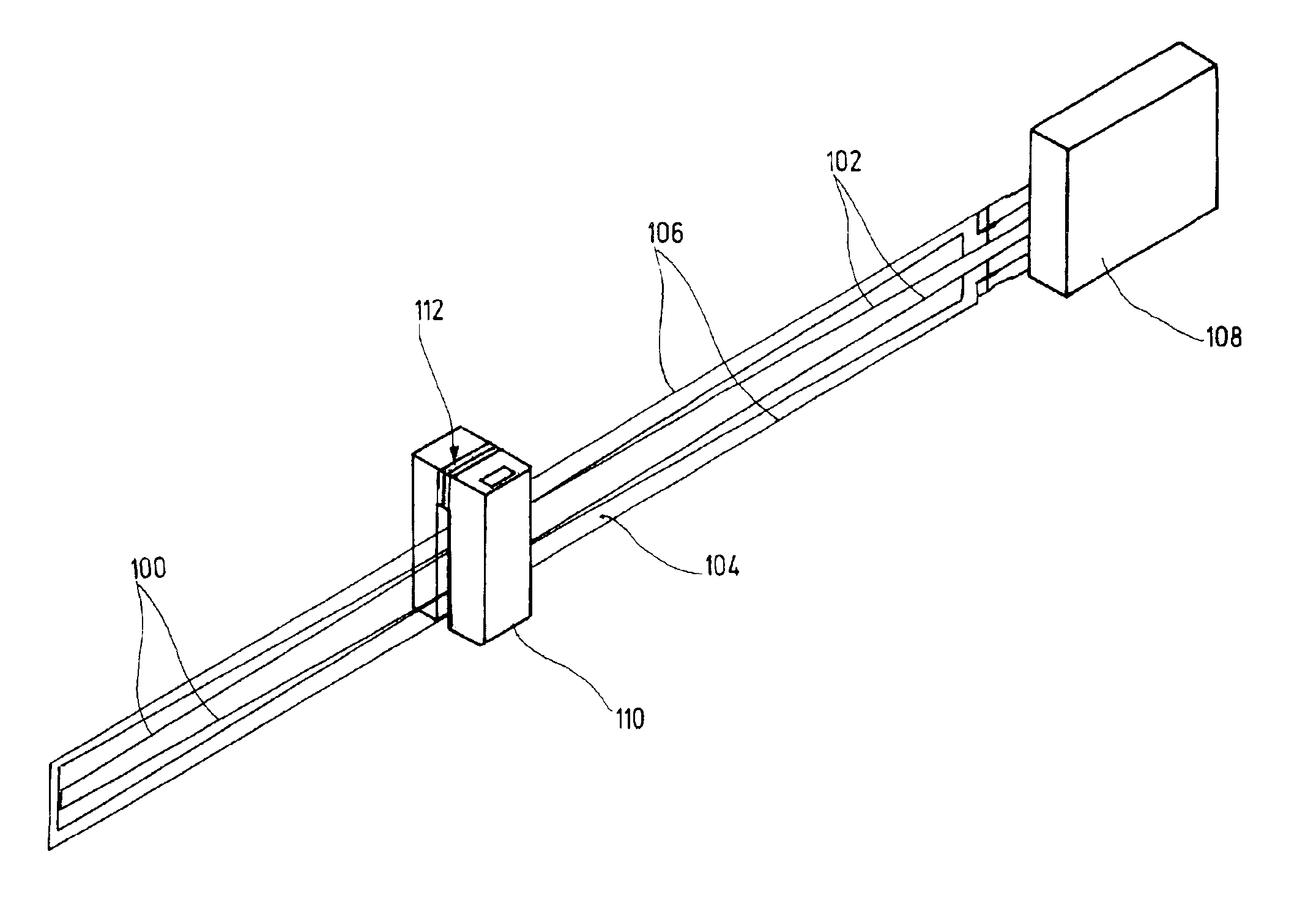
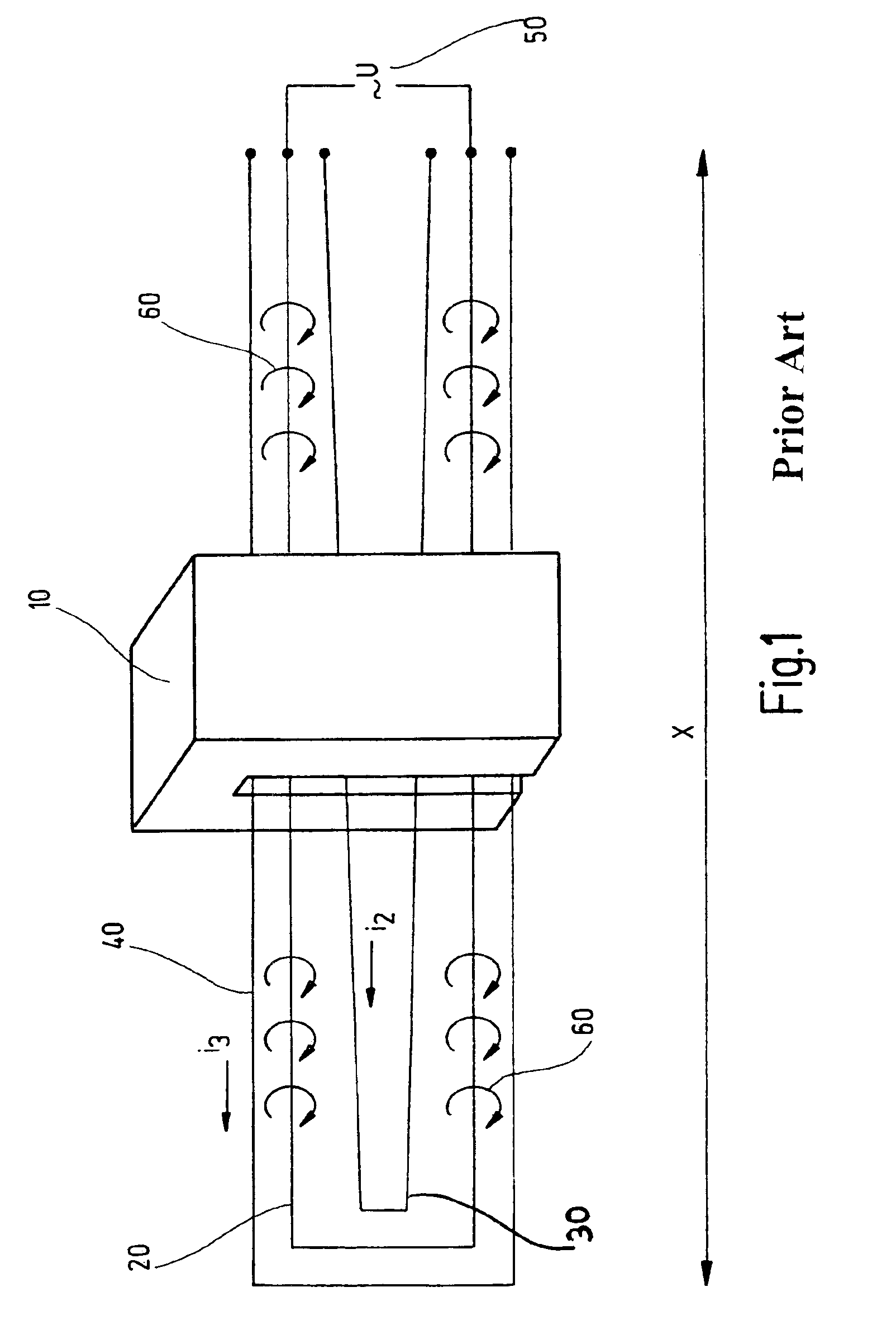
[0032]The displacement sensor shown in FIG. 1 comprises a measuring head 10 (position transducer) which can be displaced, in the indicated x direction, along an arrangement of conductor loops, namely an excitation loop 20, a measuring loop 30 and a reference loop 40. It should be noted in this connection that the measuring head 10, which is adapted to be linearly displaced, is to be regarded only as one possible example and that, on principle, any displacement curve is possible, including for example a circular or elliptical displacement curve.

[0033]The measuring head 10 consists of a magnetically permeable material, in the present case of ferrite (ferrite core), although it may also be made from a ferromagnetic or ferrimagnetic material. When an electric alternating voltage 50 is applied to the excitation loop 20, a magnetic field, indicated by magnetic lines of force 60, forms whose flux lines penetrate the inner region of the excitation loop 20 and the inner regions of the measur...


PUM


Abstract

An inductive displacement sensor having a displaceable or rotatable, magnetically permeable measuring head, at least one measuring loop whose geometric shape varies in response to the longitudinal/rotary displacement of the measuring head, and at least one excitation loop by which a magnetic flux can be generated in the measuring head. The flux penetrates the at least one measuring loop at any point of the longitudinal/rotary displacement, essentially in the region of the measuring head, and inducing an electric measuring signal (i2). A resonant circuit, which is electrically decoupled from the outside, is arranged on the measuring head and is excited in correct phase relation by a short voltage pulse after a number of, preferably, 10 to 20 free oscillations.

Description

BACKGROUND OF THE INVENTION[0001]The present invention relates to an inductive displacement sensor.[0002]An inductive displacement sensor of the before-mentioned kind has been disclosed, for example, in DE 100 16 540 C1 and FR 2 682 760 A1. The disclosed displacement sensor comprises an electrically insulated rectangular substrate with an inductor arranged thereon, which can be displaced along the substrate, which embraces the substrate in the form of a U and which serves as a displacement measuring head.[0003]The measuring head consists of a ferromagnetic material. An excitation loop of rectangular shape and a measuring loop of V-shape are provided on the substrate. When an alternating voltage is applied to the excitation loop, it induces, according to Faraday's Law, an alternating voltage in the measuring loop across the magnetic circuit forming in the measuring head and across air. Due to the geometric shape of the measuring loop, which varies continuously along the displacement ...

Claims


Application Information

Patent Timeline
Patent Type & Authority Patents(United States)
IPC IPC(8): G01D5/12G01D5/20
CPCG01D5/202
Inventor GASS, ERNSTPALI, S.ANG.NDORMELLES, .ANG.RPAD
Owner BALLUFF
Why Eureka
Try Eureka