Channeling fluidic waveguide surfaces and tubes

a fluid waveguide and surface technology, applied in the field of tubes, can solve the problems of back pressure impediment, inability to block or interrupt the noisy exhaust stream, weight and scalloping at the trailing edge of the engine nozzle, etc., to reduce frictional resistance, reduce wind resistance, and reduce frictional resistance

Inactive Publication Date: 2017-08-22
PARAFLUIDICS
View PDF46 Cites 13 Cited by
  • Summary
  • Abstract
  • Description
  • Claims
  • Application Information

AI Technical Summary

Benefits of technology

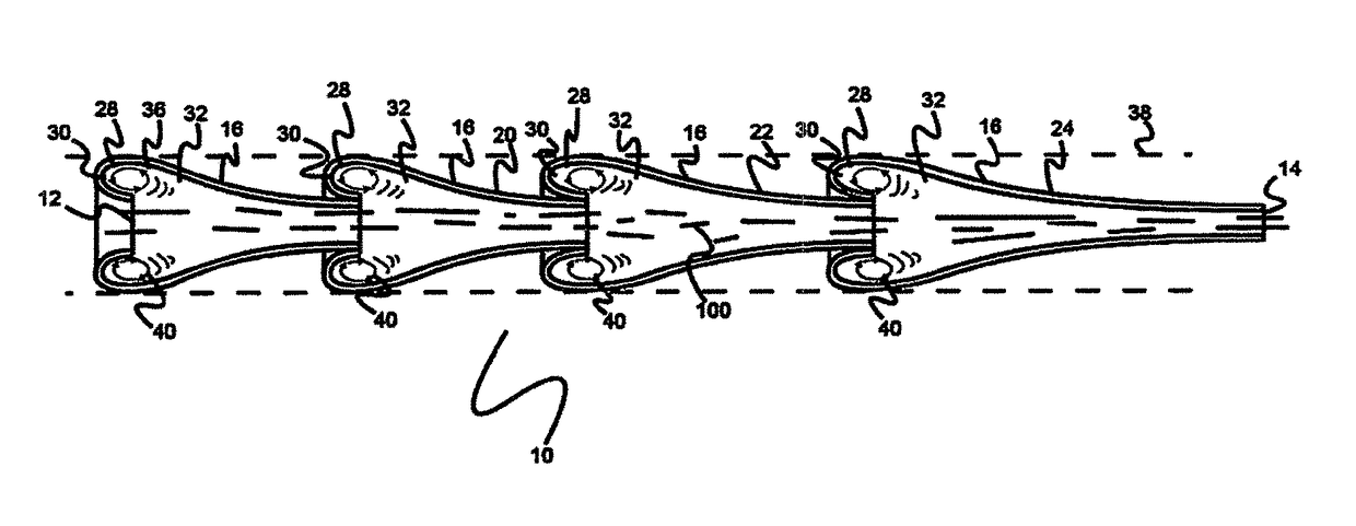
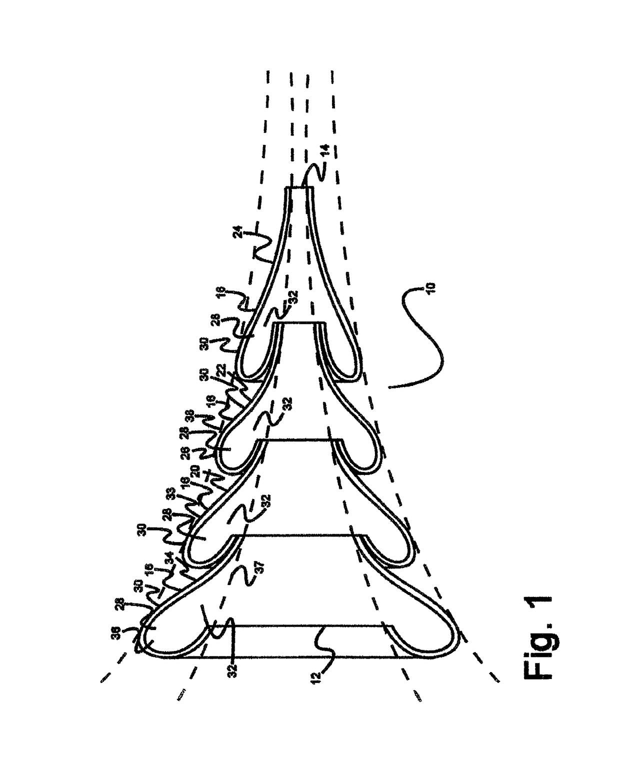
[0013]In the tubular devices of the present invention, the dual function of assisting flow and absorbing or suppressing noise energy is accomplished a structure that causes the formation of vortices in a gas flowing into an expansion chamber. Vortex creation is encouraged by providing the chamber with successive waveguides or flow guides that form annular waveguide / flow guide cavities in which vortices may form. The result is believed to be that the heat, velocity and noise in the gas stream are provided a place to translate energy into vortices which will spin within the confines of the cavities thereby absorbing the energy without impeding the flow. The result in a muffler is noise reduction without engine back pressure. In a silencer-suppressor, the result is noise reduction while organizing the blast exiting the silencer-suppressor to a more collimated form resembling a long bluish jet emanating from a 30 caliber rifle muzzle that can increase accuracy and even increase range incrementally. Without the silencer / suppressor of this invention, on the barrel the exit blast more resembled a fiery orange cloud. In aircraft applications, there is provided a technology to reduce jet engine noise beyond addition of sound absorbent padding.
[0031]Moreover, the employment of a “waveguide cavity skin” on the hulls of waterborne vehicles will reduce water resistance and improve performance. It has already been disclosed that variously defined “shark skin” surfaces may improve water flow over such surfaces. However, in this application, the inventor is proposing a surface that can be industrially formed for placement on boat hulls to improve performance.

Problems solved by technology

Such interruptions of flow are believed to have created a back pressure impediment in those devices.
In aircraft, it is not feasible to block or interrupt the noisy exhaust stream from a jet engine, so the most frequently suggested noise reduction fix was sound absorbent padding thereby adding weight and scalloping at the trailing edge of the engine nozzle.

Method used


Image

  • Channeling fluidic waveguide surfaces and tubes
  • Channeling fluidic waveguide surfaces and tubes
  • Channeling fluidic waveguide surfaces and tubes

Examples


Embodiment Construction

[0067]The inventor has conceived, and reduced to practice, channeling gas flow surfaces and tubes that address the challenges and problems in the art outlined above. Various techniques will now be described in detail with reference to a few example embodiments thereof, as illustrated in the accompanying drawings. In the following description, numerous specific details are set forth in order to provide a thorough understanding of one or more aspects and / or features described or referenced herein. However, it will be apparent to one skilled in the art, that one or more aspects and / or features described or referenced herein may be practiced without some or all of these specific details. In other instances, well known process steps and / or structures have not been described in detail in order to not obscure some of the aspects and / or features described or reference herein.

[0068]One or more different inventions may be described in the present application. Further, for one or more of the i...


PUM


Abstract

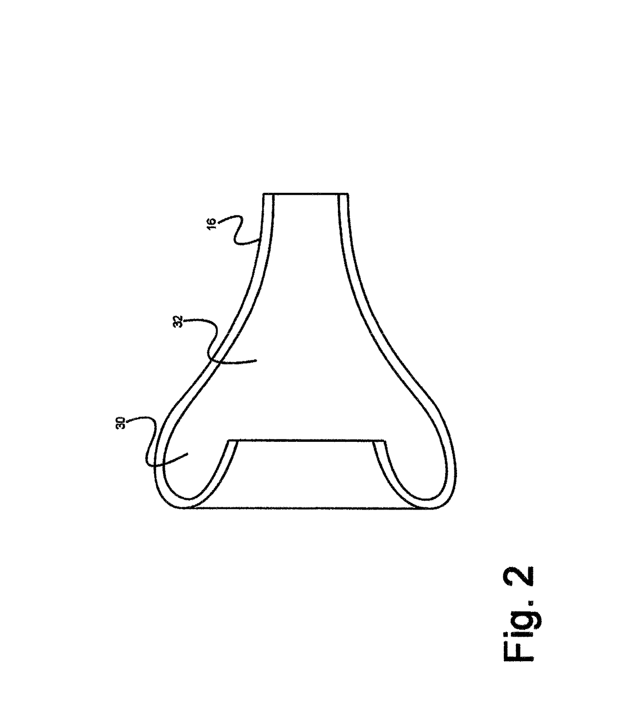
Waveguide or flow guide surfaces can improve the efficiency of fluid flow through tubes or over surfaces. When incorporated in a tube, the waveguides improve flow and function as sound absorbers making them useful in engine mufflers, firearm silencer / suppressors and jet engine exhaust attenuators. On surfaces, the waveguides can reduce fluid drag and find use on projectiles (e.g., bullets), airfoils for aircraft, and land borne vehicles. The waveguide array in either a tubular chamber or on a surface comprises a plurality of successive wave-like undulations inclined generally in the direction of flow and when employed in tubes extending inwardly to permit an unobstructed path for the fluid gas from entry to exit. The waves define annular wave cavities between their successive inwardly extending edges and the wall of the chamber with each cavity having a cavity mouth open to the unobstructed path. The waveguides are sized and spaced so that gas vortices are created within the cavities when gas flow occurs which vortices create a fluid boundary layer that assists the gas flow.

Description

RELATED APPLICATIONS[0001]This application is a continuation-in-part of U.S. patent application Ser. No. 13 / 938,213 titled “CHANNELING GAS FLOW TUBE” filed Jul. 9, 2013, which is a continuation of U.S. application Ser. No. 13 / 540,492, titled “CHANNELING GAS FLOW TUBE, filed on Jul. 2, 2012, now issued as U.S. Pat. No. 8,479,878 on Nov. 1, 2012, also titled “CHANNELING GAS FLOW TUBE”, which is a continuation-in-part of U.S. patent application Ser. No. 12 / 238,253, titled “CHANNELING GAS FLOW TUBE”, filed on Sep. 25, 2008, now issued as U.S. Pat. No. 8,210,309 on Jul. 3, 2012, the entire specifications of each of which are incorporated herein by reference.BACKGROUND OF THE INVENTION[0002]1. Field of the Invention[0003]This invention pertains to tubes having specially configured internal walls, through which a fluid may move with improved efficiency, and more particularly, to such tubes that channel gases, and articles suspended in a gas flow, centrally or axially down the tube. In a pa...

Claims


Application Information

Patent Timeline
Patent Type & Authority Patents(United States)
IPC IPC(8): F01N1/08F42B10/42F02C7/045F41A21/30F01N1/02F01N13/08G10K11/00F15D1/00B62D35/00F01N1/00
CPCF15D1/003F01N1/026F01N13/082F02C7/045F41A21/30F42B10/42G10K11/00B62D35/001F01N2470/20F01N2470/24F01N2490/155F01N2490/16F05D2260/96Y10T137/2087Y10T137/2093
Inventor SCHLOSSER, THOMAS GEORGE
Owner PARAFLUIDICS
Why Eureka
Try Eureka