Impact attenuator and vehicle, trailer and guardrail comprising such an impact attenuator

a technology of impact attenuator and attenuator body, which is applied in the direction of vibration dampers, understructures, springs/dampers design characteristics, etc. it can solve the problems of failure to assembly of said parts to at least a certain degree, friction that generates thermal energy (heat), and limited total length of impact attenuator, so as to reduce vehicle damage, increase length, and dissipate kinetic energy

Active Publication Date: 2017-08-22
VERDEGRO HLDG
View PDF20 Cites 2 Cited by
  • Summary
  • Abstract
  • Description
  • Claims
  • Application Information

AI Technical Summary

Benefits of technology

[0002]Roadside impact attenuators are intended to reduce the damage to vehicles, structures and motorists in the event of a (motor) vehicle collision by absorbing the colliding vehicle's kinetic energy. Common impact attenuators hereby deform, or more specifically split material as a method to dissipate kinetic energy. To split the material, a cutting surface is installed and configured to cut into the attenuator structure upon impact of a colliding vehicle. In common cases, the cutting surface hereby progressively splits a steel box beam in its lengthwise direction from the moment of impact up till the standstill of the vehicle. For safety reasons, it is desirable to increase the length over which the attenuator structure is split, as to lengthen the deceleration time for the vehicle as much as possible to minimize the deceleration (G-forces) experienced by the passengers. This means that, from a safety perspective, the attenuator structure must as long as practically possible. However, the total length of the impact attenuator is limited due to transportation requirements. Especially attenuators suited for temporary use in road construction projects or truck mounted attenuators are frequently transported and need to conform to the height, width and length requirements set for road transport.
[0003]An object of the specification is therefore to provide an impact attenuator that offers improved safety, better transportability and / or at least provides a useful alternative to the state of the art.SUMMARY

Problems solved by technology

However, the total length of the impact attenuator is limited due to transportation requirements.
Consecutively, the absorbed energy is (at least partly) dissipated by the splitting action of the cutting edges, which plastically deforms the energy absorption body and causes friction that generates thermal energy (heat).
This creates essentially self-contained parts of the energy absorption body that work independently, making the assembly of said parts fail-safe to at least a certain degree.

Method used


Image

  • Impact attenuator and vehicle, trailer and guardrail comprising such an impact attenuator
  • Impact attenuator and vehicle, trailer and guardrail comprising such an impact attenuator
  • Impact attenuator and vehicle, trailer and guardrail comprising such an impact attenuator

Examples


Embodiment Construction

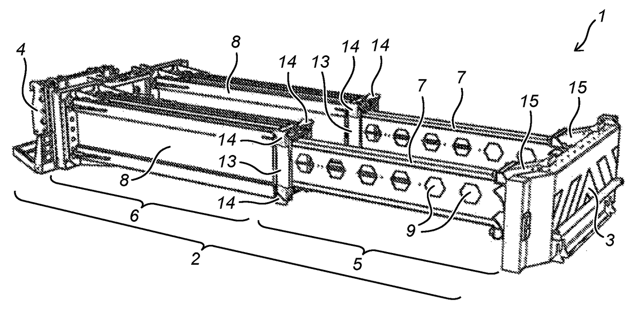
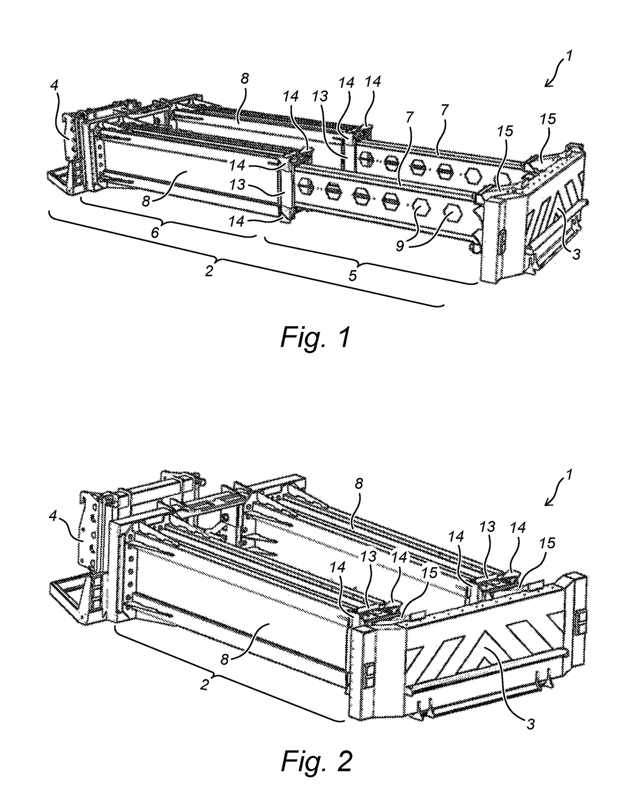
[0039]FIG. 1 shows a three-dimensional view of a preferred embodiment of an impact attenuator 1 according to the specification. The impact attenuator 1 is shown in an extended position, which corresponds to the attenuator's operational configuration. The impact attenuator 1 comprises an energy absorption body 2, on a first end provided with an impact head 3 and on a second end opposing the first end coupled to an external structure by means of an adjustable coupling 4. Although the adjustable coupling 4 as shown here allows specifically for coupling the impact attenuator 1 to trucks or other vehicles, the impact attenuator 1 could also be coupled to or be part of other external structures, not exclusively including trailers (see for example FIG. 2), guardrails (see for example FIG. 10) and ground anchors. The energy absorption body 2 comprises a first part 5 and a second part 6, extending past each other in a lengthwise direction, wherein the first part comprises two H-beam structur...


PUM


Abstract

An impact attenuator including an impact head, coupled to a first end of an energy absorption body, which energy absorption body is arranged for fixation to an external structure at a second end opposing the first end of the energy absorption body, configured to at least partly absorb or dissipate energy from a collision of an object with the impact head, and including a first part and a second part extending substantially lengthwise behind each other, wherein the first and second part are mutually moveable and including a first and a second cutting edge, wherein, the first cutting edge is arranged for splitting the first part of the energy absorption body upon impact of an object colliding with the impact head, and the second cutting edge is arranged for consecutively splitting the second part of the energy absorption body upon impact of an object colliding with the impact head.

Description

TECHNICAL FIELD[0001]The following specification relates to an impact attenuator for roadside application, suited for reducing the severity of a collision by absorbing at least part of the kinetic energy of an object, and specifically a vehicle, colliding with said impact attenuator. The specification furthermore relates to a vehicle comprising such an impact attenuator, a trailer comprising such an impact attenuator and a guardrail comprising such an impact attenuator.SUMMARY[0002]Roadside impact attenuators are intended to reduce the damage to vehicles, structures and motorists in the event of a (motor) vehicle collision by absorbing the colliding vehicle's kinetic energy. Common impact attenuators hereby deform, or more specifically split material as a method to dissipate kinetic energy. To split the material, a cutting surface is installed and configured to cut into the attenuator structure upon impact of a colliding vehicle. In common cases, the cutting surface hereby progressi...

Claims


Application Information

Patent Timeline
Patent Type & Authority Patents(United States)
IPC IPC(8): E01F15/00F16F7/12E01F15/14E01F15/04B62D63/06B62D21/15
CPCF16F7/123B62D21/152B62D63/062E01F15/04E01F15/146F16F2230/0023E01F15/148E01F15/143
Inventor DEGROOT, SJOERDVERWIJS, GERRIT
Owner VERDEGRO HLDG
Why Eureka
Try Eureka