Plasma processing method and plasma processing apparatus

a processing method and plasma technology, applied in the direction of electrical apparatus, decorative surface effects, electric discharge tubes, etc., can solve the problems of gate oxide film charging damage and difficulty in controlling etching depth

Active Publication Date: 2017-09-05
TOKYO ELECTRON LTD
View PDF9 Cites 28 Cited by
  • Summary
  • Abstract
  • Description
  • Claims
  • Application Information

AI Technical Summary

Benefits of technology

[0019]In accordance with the plasma processing apparatus and the plasma processing method of the example embodiments, it is possible to start a plasma process under preset processing conditions stably and securely by igniting plasma securely even when a duty ratio or a pulse frequency is set to be any specific value in the power modulation of modulating a high frequency power for plasma generation to a pulse shape.

Problems solved by technology

However, if the ion energy is lowered at a lower pressure, the non-uniformity of the plasma potential in the entire surface of the substrate may easily cause the charging damage on a gate oxide film.
That is, an etching rate may differ depending on the hole size, so that it is difficult to control an etching depth.

Method used


Image

  • Plasma processing method and plasma processing apparatus
  • Plasma processing method and plasma processing apparatus
  • Plasma processing method and plasma processing apparatus

Examples


modification examples

[0141]Other example embodiments or modification examples

[0142]From the foregoing, it will be appreciated that various embodiments of the present disclosure have been described herein for purposes of illustration, and that various modifications may be made without departing from the scope and spirit of the present disclosure

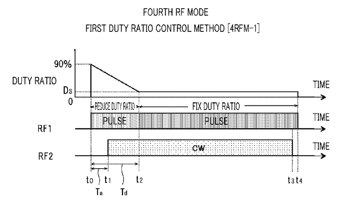
[0143]By way of example, as shown in FIG. 21A, it may be possible to perform a control of reducing a duty ratio of the power modulation from an initial value (e.g., about 90% in the shown example) to a set value Ds in step shape during a transition time Td immediately after a process is started. Alternatively, as depicted in FIG. 21B, it may be also possible to perform a control of reducing a duty ratio to the set value Ds gradually (or in step shape) after a lapse of a certain elapse time Tk immediately after the process is started. Here, in the aspect of performing a plasma process as desired under desired processing conditions, it may be desirable to shorten th...


PUM


Abstract

At a time point T0 when starting a process, a duty ratio of a high frequency power RF1 to which power modulation is performed is set to be an initial value (about 90%) which allows plasma to be ignited securely under any power modulating conditions. At the substantially same time of starting the process, the duty ratio of the high frequency power RF1 is gradually reduced from the initial value (about 90%) in a regular negative gradient or in a ramp waveform. At a time point t2 after a lapse of a preset time Td, the duty ratio has an originally set value Ds for an etching process. After the time point t2, the duty ratio is fixed or maintained at the set value Ds until the end (time point T4) of the process.

Description

CROSS-REFERENCE TO RELATED APPLICATION[0001]This Application is a U.S. national phase application under 35 U.S.C. §371 of PCT Application No. PCT / JP2012 / 007727 filed on Dec. 3, 2012, which claims the benefit of Japanese Patent Application No. 2011-270356 filed on Dec. 9, 2011, and U.S. Provisional Application Ser. No. 61 / 577,743 filed on Dec. 20, 2011, the entire disclosures of which are incorporated herein by reference.TECHNICAL FIELD[0002]The embodiments described herein pertain generally to a technique of performing a plasma process on a processing target substrate; and, more particularly, the embodiments pertain to a capacitively coupled plasma processing apparatus and a plasma processing method in which a high frequency power for plasma generation is modulated in a pulse shape.BACKGROUND ART[0003]A capacitively coupled plasma processing apparatus includes an upper electrode and a lower electrode arranged in parallel to each other within a processing vessel. A processing target ...

Claims


Application Information

Patent Timeline
Patent Type & Authority Patents(United States)
IPC IPC(8): B44C1/22H01J37/32
CPCH01J37/32568H01J37/32091H01J37/32146
Inventor YAMADA, NORIKAZUTACHIKAWA, TOSHIFUMINAGAMI, KOICHI
Owner TOKYO ELECTRON LTD
Why Eureka
Try Eureka