Recording medium data recording method and device

a recording method and data technology, applied in the field of recording medium data recording methods and devices, can solve the problems of inability to make normal marks, inability to generate write beam pulses accurately, and inability to make marks according to the property of the storage medium

Inactive Publication Date: 2006-12-07
PANASONIC CORP
View PDF11 Cites 25 Cited by
  • Summary
  • Abstract
  • Description
  • Claims
  • Application Information

AI Technical Summary

Benefits of technology

[0020] A data recording method according to the present invention is a method for recording data as edge position information, including marks and spaces of multiple different lengths, on a storage medium by irradiating the storage medium with a pulsed energy beam. The method includes the steps of: (A) generating a write code sequence based on the data to be recorded; (B) determining a write pulse waveform, defining the power modulation of the energy beam, according to the code lengths of respective codes included in the write code sequence; and (C) modulating the power of the energy beam based on the write pulse waveform. If the shortest code length of the write code sequence is n (which is an integer equal to or greater than one), the step (B) includes assigning a write pulse waveform that has only one write pulse to recording mark making periods corresponding to codes with code lengths x of n, n+1 and n+2, and a write pulse waveform that has multiple write pulses Pw to recording mark making periods corresponding to codes with code lengths x of n+3 or more, respectively.

Problems solved by technology

However, it usually takes several nanoseconds to activate a semiconductor laser, and it is difficult to generate a write beam pulse accurately.
Also, even if a write beam pulse could be generated accurately, normal marks could not be made in a situation where multi-pulse writing is carried out on a medium such as a phase change disk in which the mark making is controlled by the cooling rate of its heated portion.
Consequently, marks could not be made properly depending on the property of the storage medium.
However, this conventional technique does not consider thermal balance between write pulses for respective elements at all.
That is why as the recording linear density is increased, it becomes more and more difficult to control the mark edge position.
As a result, the edge recording cannot be carried out as intended.
In a read / write drive that determines read / write conditions by detecting the average level of a read signal, however, such distortion of the read signal should affect the operation of the drive.
However, since the read signal of the phase pit type storage medium has no such distortion, it is actually difficult to read the phase change storage medium and phase pit type storage medium using the same drive.
Also, according to the fourth conventional technique, the write power level of the write pulse train changes stepwise, thus requiring complicated power control.
When a very small mark needs to be made on a high-density storage medium in the near future, such an emission time will be too long to make desired recording marks.
As can be seen, none of the conventional techniques mentioned above can contribute to making marks sufficiently accurately when the transfer rate is high or achieving sufficiently high storage plane density and reliability.

Method used


Image

  • Recording medium data recording method and device
  • Recording medium data recording method and device
  • Recording medium data recording method and device

Examples


embodiment 1

[0062] A first preferred embodiment of a data recorder according to the present invention will be described.

[0063] In this preferred embodiment, a phase change optical disk is used as a storage medium. However, the storage media that may be used in the present invention are not limited to optical disks of that type. Any other type of storage medium can also be used effectively in the present invention as long as the storage medium can locally make a “mark” with a different physical property from the other portions by applying some non-optical energy such as magnetic energy or electron beam to the storage medium.

[0064] The present invention is characterized by its write strategy of controlling the level of energy applied to a storage medium in recording data on the storage medium (i.e., write energy) highly precisely. As used herein, the “write energy level” means the average energy level of a laser beam in a period of time that is approximately a half as long as the detection wind...

embodiment 2

[0114] Hereinafter, a data recording method according to a second preferred embodiment of the present invention will be described with reference to FIG. 6.

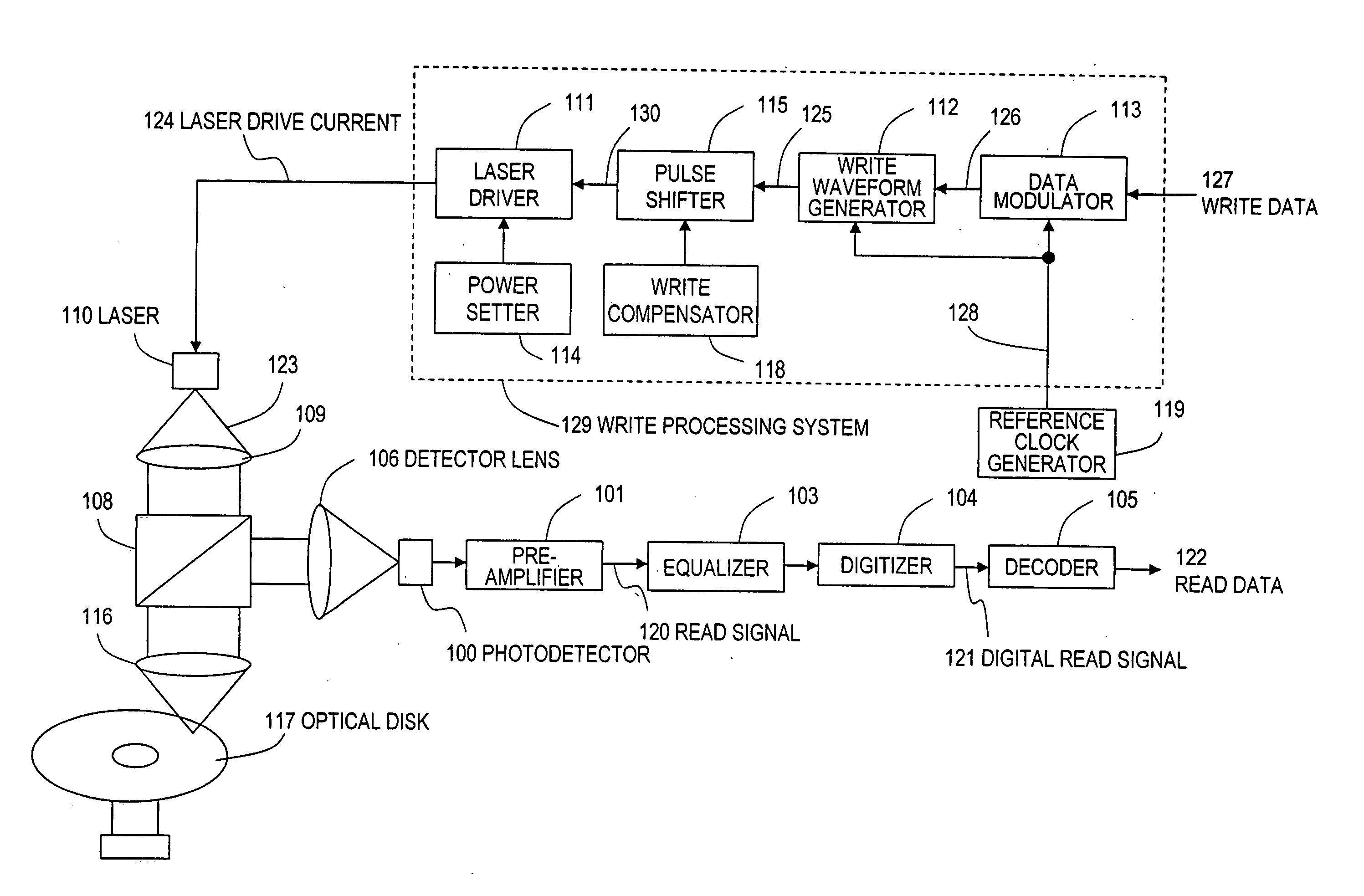
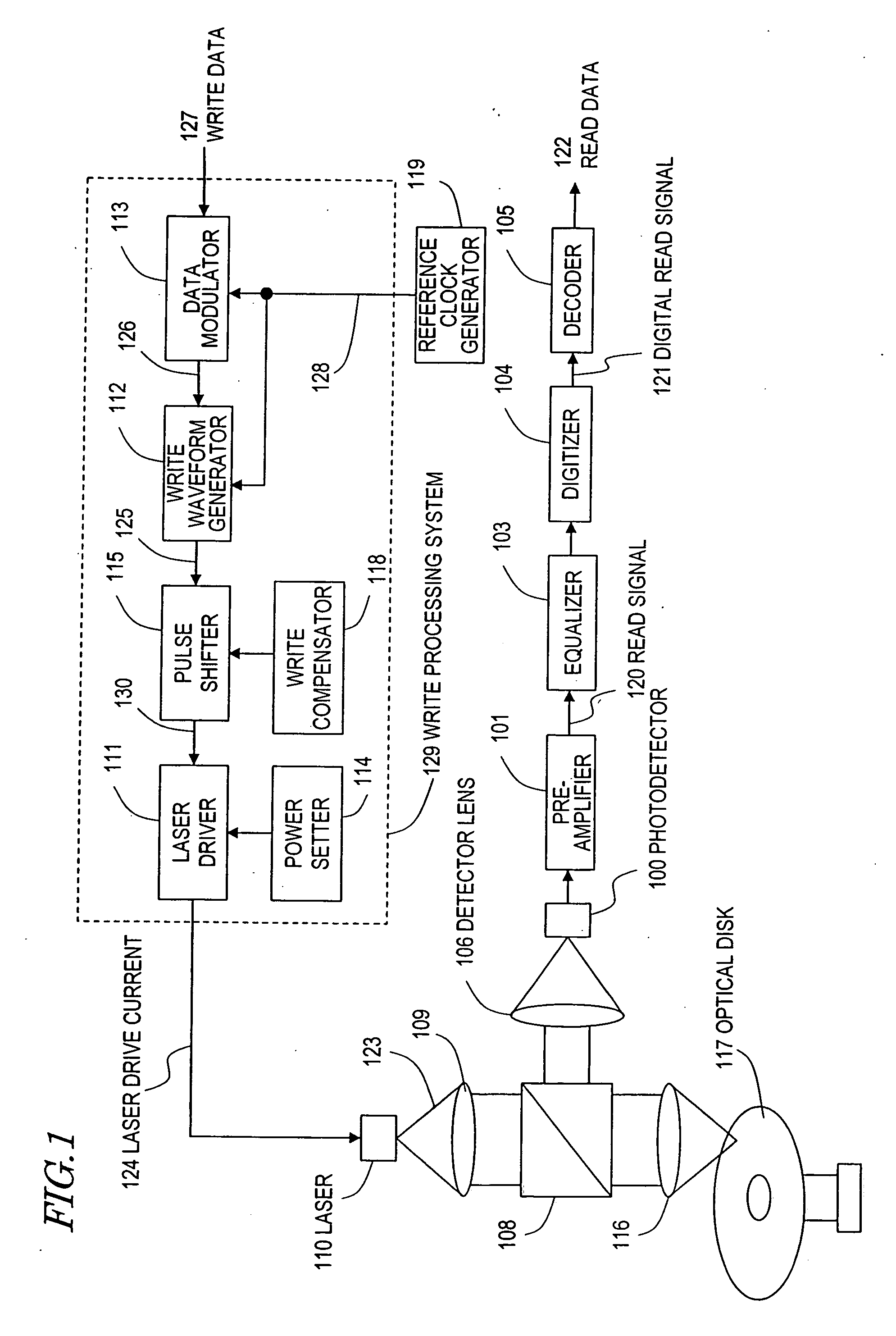
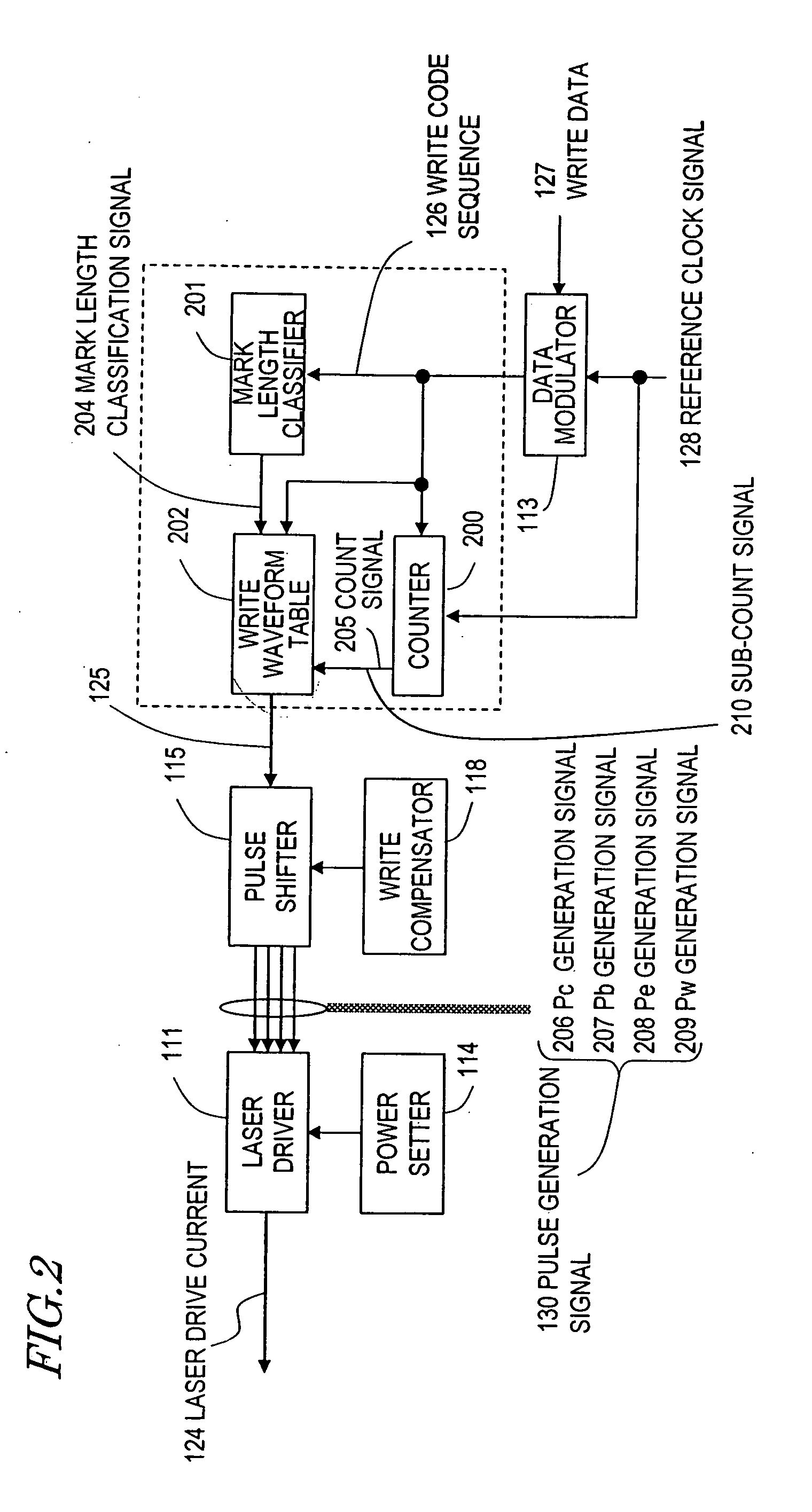
[0115] The data recording method of this preferred embodiment can be carried out just by modifying the operation program for the data recorder of the first preferred embodiment described above. That is why the data recorder for use in this preferred embodiment has substantially the same configuration as the counterpart shown in FIGS. 1 and 2, and detailed description thereof will be omitted herein.

[0116] The write pulse waveforms 600 through 607 of this preferred embodiment will be described. with reference to portions (a) through (j) of FIG. 6.

[0117] As can be seen easily by comparing portions (a) through (j) of FIG. 6 to the counterparts of FIG. 4, the signal waveforms 600 through 607 adopted in this preferred embodiment are similar to the signal waveforms 400 through 407 shown in FIG. 4. Among other things, the signal wavefo...

embodiment 3

[0124] Hereinafter, a data recording method according to a third preferred embodiment of the present invention will be described with reference to FIG. 7.

[0125] The data recording method of this preferred embodiment can be carried out just by modifying the operation program for the data recorder of the first preferred embodiment described above. That is why the data recorder for use in this preferred embodiment has substantially the same configuration as the counterpart shown in FIGS. 1 and 2, and detailed description thereof will be omitted herein.

[0126] The write pulse waveforms 700 through 707 of this preferred embodiment will be described with reference to portions (a) through (j) of FIG. 7.

[0127] As can be seen easily by comparing portions (a) through (j) of FIG. 7 to the counterparts of FIG. 6, the signal waveforms 700 through 707 adopted in this preferred embodiment are similar to the signal waveforms 600 through 607 shown in FIG. 6. The difference between the second and t...


PUM

PropertyMeasurementUnit
wavelengthaaaaaaaaaa
frequencyaaaaaaaaaa
wavelengthaaaaaaaaaa

Abstract

A data recording method according to the present invention is a method for recording data as edge position information, including marks and spaces of multiple different lengths, on a storage medium by irradiating the storage medium with a pulsed energy beam. The method includes the steps of: (A) generating a NRZI data based on the data to be recorded; (B) determining a write pulse waveform, defining the power modulation of the energy beam, according to the code lengths of respective codes included in the NRZI data; and (C) modulating the power of the energy beam based on the write pulse waveform. If the shortest code length of the NRZI data is n (which is an integer equal to or greater than one), a write pulse waveform that has only one write pulse is assigned to recording mark making periods corresponding to codes with code lengths x of n, n+1 and n+2, and a write pulse waveform that has multiple write pulses Pw is assigned to recording mark making periods corresponding to codes with code lengths x of n+3 or more.

Description

TECHNICAL FIELD [0001] The present invention relates to a method and apparatus for recording data (or information) on a storage medium such as an optical disk by irradiating the storage medium with a laser beam or any other energy beam so as to make a mark having a different physical property from a non-recorded portion thereof. BACKGROUND ART [0002] A rewritable optical disk such as a DVD-RAM has a phase change recording layer on its substrate. When this phase change recording layer is irradiated with a laser beam having a high energy density, the irradiated portion is locally heated to a temperature exceeding the melting point and melted. Since the optical disk being irradiated with the laser beam is spinning at a high velocity, the beam spot of the laser beam will be moving along the track on the phase change recording layer at a high velocity, too. That is why that portion of the phase change recording layer that has been melted by the passage of the beam spot is quickly cooled ...

Claims


Application Information

Patent Timeline
Patent Type & Authority Applications(United States)
IPC IPC(8): G11B27/30G11B7/0045G11B7/006G11B7/125
CPCG11B7/0062G11B7/0045G11B7/1263
Inventor NAKAMURA, ATSUSHIFURUMIYA, SHIGERU
Owner PANASONIC CORP
Why Eureka
Try Eureka