Recording clock generating device and method thereof

a recording clock and generating device technology, applied in the direction of recording signal processing, digital signal error detection/correction, instruments, etc., can solve the problems of increasing circuit scale, recording clock jitter, and wiggle phase not matching from track to track

Inactive Publication Date: 2005-02-15
JVC KENWOOD CORP A CORP OF JAPAN +1
View PDF9 Cites 27 Cited by
  • Summary
  • Abstract
  • Description
  • Claims
  • Application Information

AI Technical Summary

Benefits of technology

In this case, it is also possible to detect the phase difference between the recording clock and prepits at the clock, and by inserting a low-pass filter, shifting of the PLL phase due to prepit detection errors can be prevented. A single PLL can also be effectively used for recording clock phase correction.

Problems solved by technology

This is particularly a problem with DVD-R media, which is written with a CLV format, because if the wobble phase shifts in each rotation of the disk, the wobble phase will not match from track to track.
A further problem is that if the wobble period fluctuates in an area where there are no land prepits, recording clock jitter increases.
The problem with this configuration is the circuit scale increases.
The problem with a 140 kHz wobble frequency PLL is that the low frequency makes integration into modern digital chips difficult.
If many analog PLL components such as charge pumps and VFO devices are built in to a digital chip, chip size increases, high precision noise management is required to assure the desired PLL jitter performance, and chip design is thus made more difficult.
A further problem is the basic incompatibility between the analog phase shift circuit and a digital chip design.
More specifically, the wobble signal edge shifts when a land prepit is near the slice level for digitizing the wobble, and the wobble signal period is therefore not correct.
However, some effect of power modulation remains in the push-pull signal and power modulation near the slice level for digitizing the wobble shifts the wobble signal edge so that the wobble signal period is not correct.
If this difference is passed straight through the bandpass filter and digitized, the amplifier will be saturated during recording and the signal will be buried in noise during reproduction.
However, correct digitizing cannot be expected during the transient states immediately after the start and end of recording, the wobble signal period will vary greatly, and wobble signal detection will be difficult for a time.
Yet further, land prepit detection also has a high frequency jitter component as a result of the recording power fluctuation discussed in the third problem above.
Finally, no specific solution for the second to fifth problems described above is known from the prior art.

Method used


Image

  • Recording clock generating device and method thereof
  • Recording clock generating device and method thereof
  • Recording clock generating device and method thereof

Examples


first embodiment

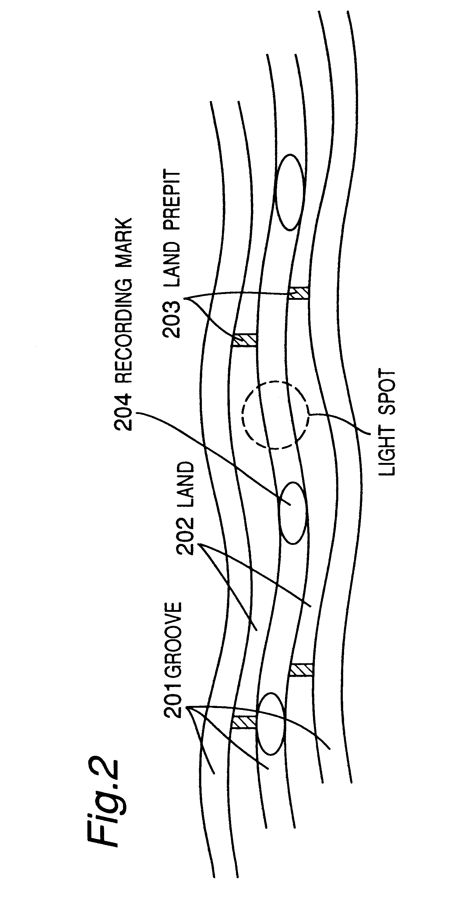
The typical groove configuration of a disk as conceived by the present invention is shown in FIG. 2. Shown in FIG. 2 are a groove 201, land 202, a land prepit 203 that is formed on a land, and a recording mark 204 that is recorded to a groove. The undulations in the recording grooves are called “wobble” and are used to detect the linear velocity of the disk. The land prepits are used to generate the recording clock and for CLV control. In DVD-R and DVD-RW discs, the wobble period is 186 times the recording clock frequency. The land prepits 203 are encoded with address information and are used for detecting a precise location on the disk.

The recording format of the disk is shown in FIG. 3. As shown in FIG. 3, the recording format 301 has 26 frames per sector; one frame has a length of eight wobble periods. A photodetector which is divided into plural photodetection segments in a line that is substantially parallel to the tracking direction detects light that is reflected from the gro...

second embodiment

This second embodiment of the present invention can smoothen the change in the timer output period as compared with the first embodiment, and can be expected to improve jitter in the recording clock which is obtained by multiplying the timer output, by updating the period average every wobble period. In addition, by reflecting the wobble signal and the timer output phase difference in the timer setting, the accumulation of period averaging rounding error and timer resolution error can be suppressed, and the wobble signal and timer output can be kept in phase.

Third Embodiment

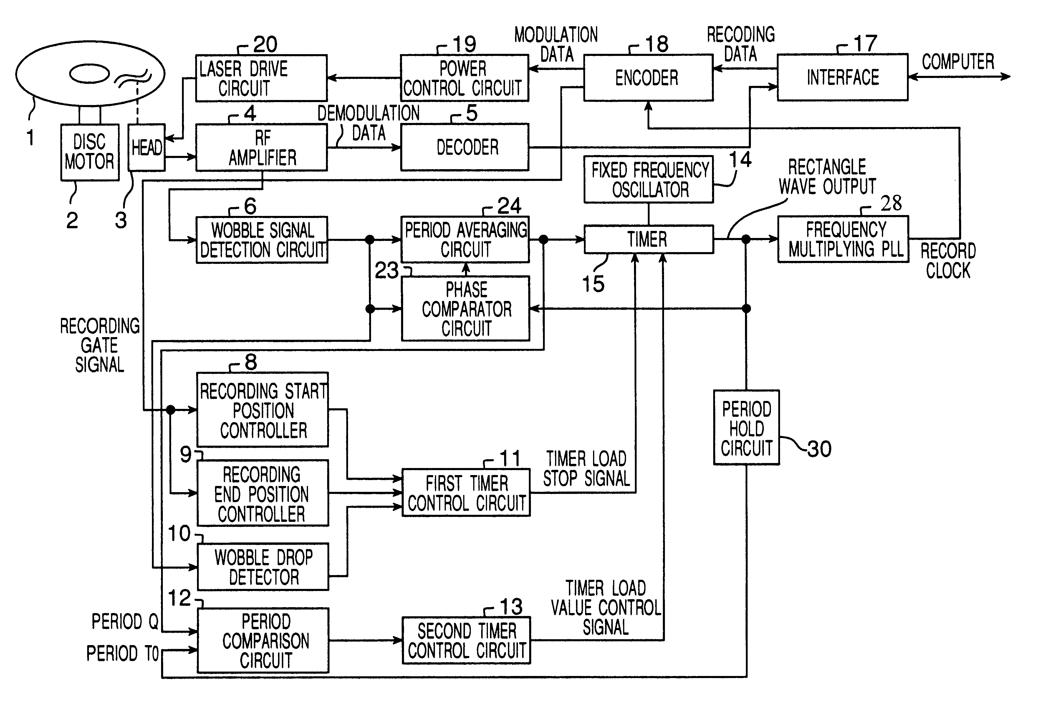
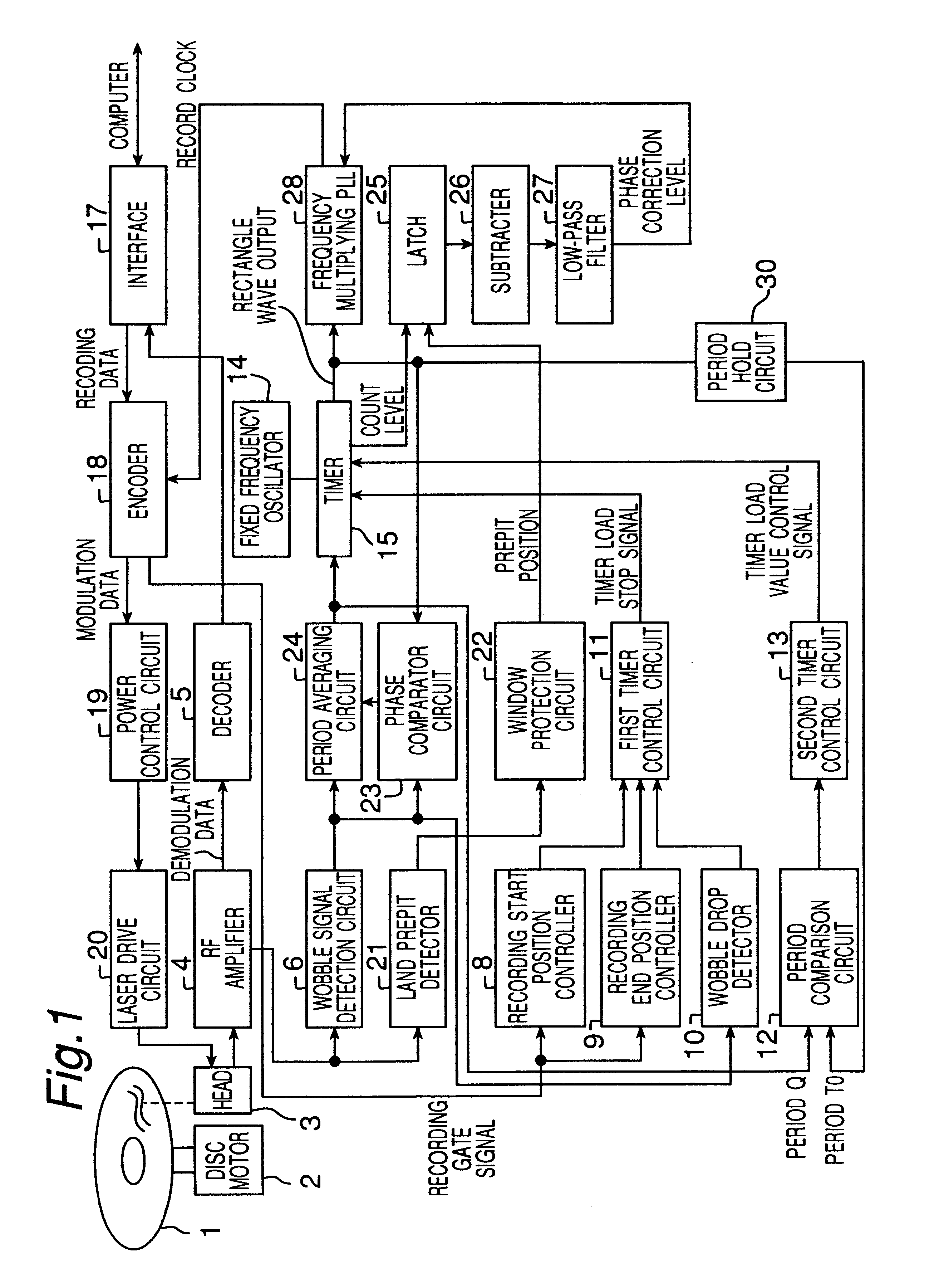
FIG. 1 is a block diagram of a third embodiment of the present invention. As shown in FIG. 1 this third embodiment has the optical disk 1, disk motor 2, head 3, RF amplifier 4, decoder 5, wobble signal detection circuit 6, recording start position controller 8, recording end position controller 9, wobble drop detector 10, first timer control circuit 11, period comparison circuit 12, second timer control circuit 1...

third embodiment

This third embodiment of the present invention can easily detect the phase of the wobble signal and the land prepit signal and can correct the phase of the recording clock using the land prepit signal by effectively combining a frequency multiplying PLL with a small scale, digitally configurable period averaging circuit and low-pass filter.

The wobble frequency is 140 kHz, the land prepits appear every two frames (approximately 10 kHz), the PLL response band from tracking disk eccentricity is approximately 1 kHz, and wobble interference between tracks has a relatively slow period of 5.3 revolutions in DVD-R media. The timer phase correction response speed of 140 kHz in the period averaging circuit is therefore sufficient to measure the phase difference between the wobble signal and the land prepits appearing at approximately 10 kHz. Furthermore, by setting the cutoff frequency of the low-pass filter to approximately 1 kHz, it is possible to phase correct the frequency multiplying PLL...


PUM

PropertyMeasurementUnit
frequencyaaaaaaaaaa
frequencyaaaaaaaaaa
wobble frequencyaaaaaaaaaa

Abstract

Crosstalk between tracks, land prepit leakage, and effects of recording power modulation can cause the wobble signal period to change irregularly, thereby producing jitter in the recording clock which is derived by frequency multiplying the wobble signal. This problem is resolved by a recording clock generating circuit having an arrangement to average the wobble signal period, a timer for generating a rectangular wave with substantially the same period as the average period, and a frequency multiplying PLL for multiplying the timer output. The period averaging arrangement in particular determines the approximate average period at every wobble period and reflects the phase difference between the wobble signal and the timer in the timer setting so as to improve recording clock stability.

Description

BACKGROUND OF THE INVENTION1. Field of the InventionThe present invention relates to a device for generating a recording clock for recording to an optical disk, typically DVD-R or DVD-RW media, having wobbled recording grooves, and a method thereof.2. Description of the Related ArtA typical method for generating the recording clock for recording to an optical disk having wobbled recording grooves such as those that are printed to DVD-R media is known, for example, from Japanese Patent Laid-Open Publication (kokai) H10-293926. The wobble signal is a continuous signal with a frequency component that is synchronized to disk rotation. The cited method uses this characteristic to generate a recording clock signal that is precisely synchronized to disk rotation by generating a clock signal phase that is synchronized to the continuous signal with a frequency multiplied PLL. The wobble signal is produced by detecting reflection from the groove by using a detector which is segmented in the t...

Claims


Application Information

Patent Timeline
Patent Type & Authority Patents(United States)
IPC IPC(8): G11B27/19G11B20/14G11B27/24G11B7/007G11B27/30G11B7/0045G11B7/00H03L7/18H03L7/16
CPCG11B7/00718G11B20/1426G11B27/24G11B7/0045H03L7/18G11B2020/1446G11B2220/216G11B2220/218G11B2220/2562G11B27/3027
Inventor USUI, MAKOTODEGUCHI, HIRONORIOCHI, TAKAHIROUEKI, YASUHIROOHTA, MITSUHIKOOSADA, YUTAKA
Owner JVC KENWOOD CORP A CORP OF JAPAN
Why Eureka
Try Eureka