Device and method for the geometric determination of electrical dipole densities on the cardiac wall

a technology of electrical dipole density and geometric determination, which is applied in the field of localization and treatment of cardiac arrhythmias, can solve the problems of limited success and reliability, and the success of cardiac arrhythmia treatment has been difficult, and achieve the effect of improving long-term patient outcomes

Active Publication Date: 2017-09-12
ACUTUS MEDICAL INC
View PDF115 Cites 32 Cited by
  • Summary
  • Abstract
  • Description
  • Claims
  • Application Information

AI Technical Summary

Benefits of technology

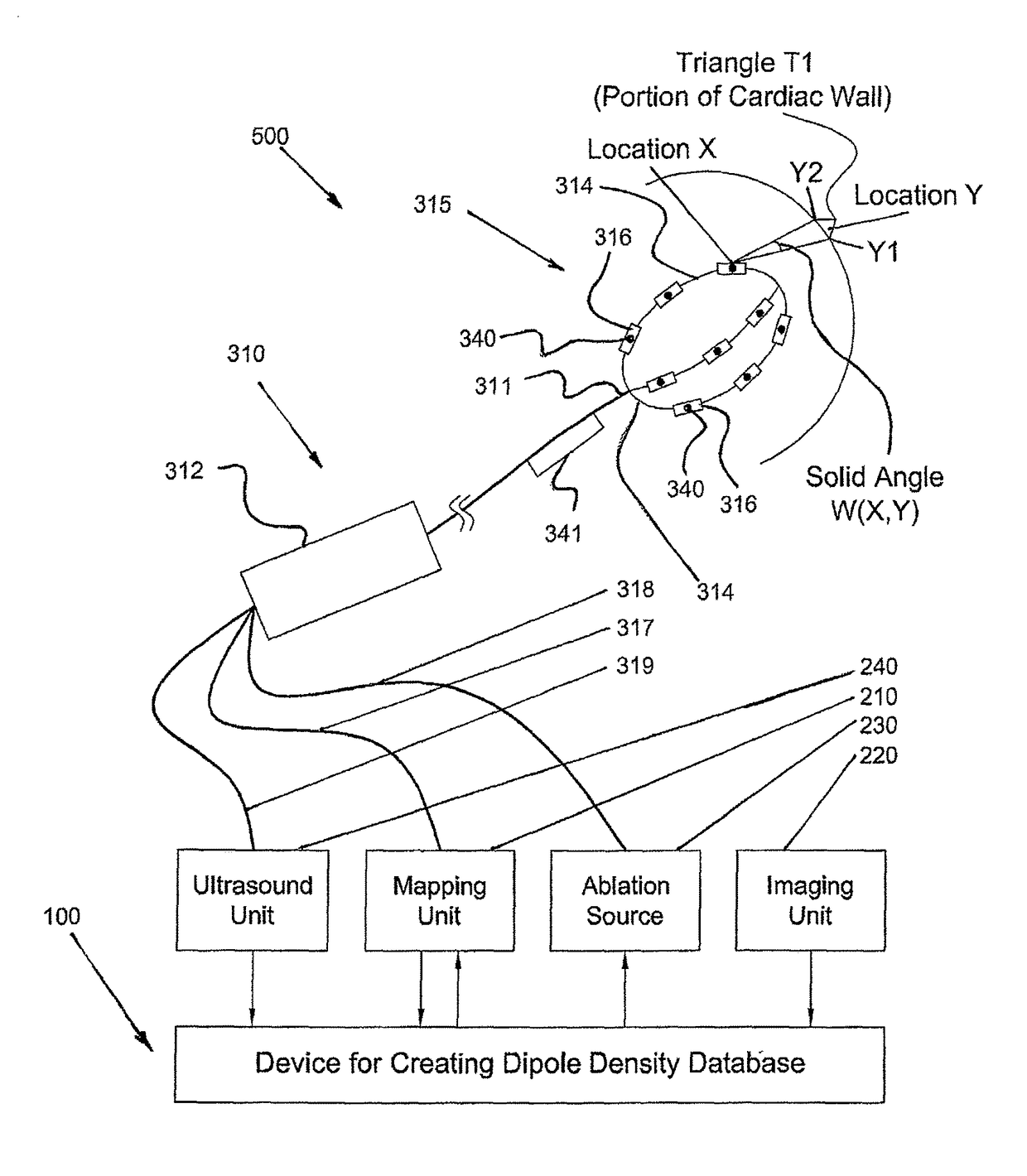
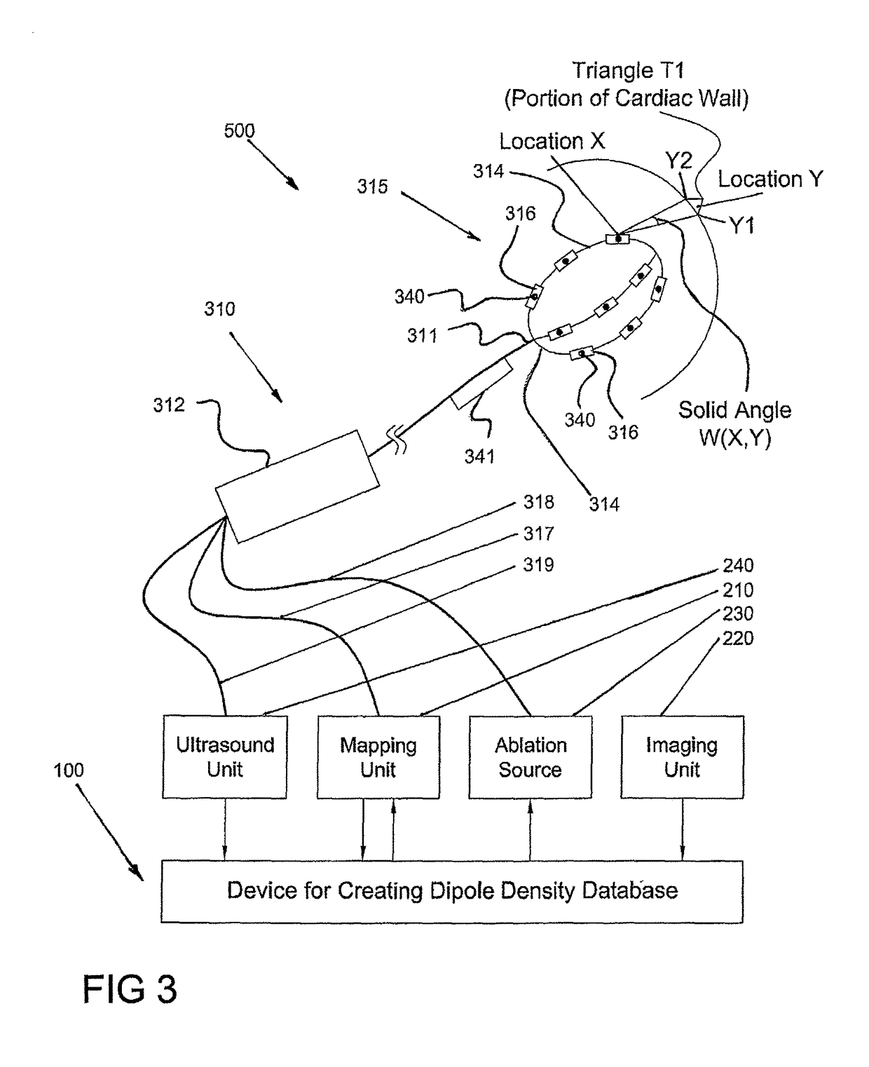
[0007]In some embodiments, the device may include a catheter which is further configured as a delivery sheath. For example, a first catheter may comprise a lumen, such that a separate ablation catheter may be slidingly received by the first catheter. Additionally, a single sheath may be provided to allow the first catheter and the ablation catheter to pass there though. This construction would eliminate the need for multiple sheath devices.
[0033]The method may further comprise ablating the cardiac tissue based upon the tissue diagnosis. For example, the anatomical information comprises tissue thickness information and at least one of the ablation energy or the time period is adjusted based on the tissue thickness information. A clinician may assess the tissue during and post ablation to assess changes in the tissue due to the application of the ablation energy. For example, the clinician may also use information received form one or more ultrasound sensors in combination with dipole density mapping information received from one or more electrodes to assess the adequacy of tissue ablation, such as to improve long-term patient outcomes.

Problems solved by technology

Another limitation of the current methods is that the provided potentials represent only the mean electrical activity summed across a large region of tissue, with cells consisting of membranes separating electrical dipoles.
Since the localization of cardiac arrhythmias by the use of potentials is imprecise, the successful treatment of cardiac arrhythmias has been difficult and has demonstrated limited success and reliability.

Method used


Image

  • Device and method for the geometric determination of electrical dipole densities on the cardiac wall
  • Device and method for the geometric determination of electrical dipole densities on the cardiac wall
  • Device and method for the geometric determination of electrical dipole densities on the cardiac wall

Examples


case 1

[0296]More specifically, the following four cases may exist:[0297] Electrical and anatomical are adequate—Tissue is healthy,[0298]Case 2: Electrical is adequate and anatomical is inadequate—Tissue is compromised,[0299]Case 3: Electrical is inadequate and anatomical is adequate—Tissue is compromised, and[0300]Case 4: Electrical and anatomical are both inadequate—Tissue necrosis.

[0301]The actual threshold for determining adequacy of electrical function of any one area of the heart is dependent upon many factors, including the degree of coordination of the activation pattern and the mass of the cells being activated. Additionally, this threshold will be different for each chamber of the heart as well as from smaller to larger patients. For example, a threshold of 0.5 mV may be appropriate, wherein an electrical potential smaller that 0.5 mV may be indicative of inadequate electrical function and an electrical potential at or larger than 0.5 mV may be indicative of adequate electrical f...


PUM


Abstract

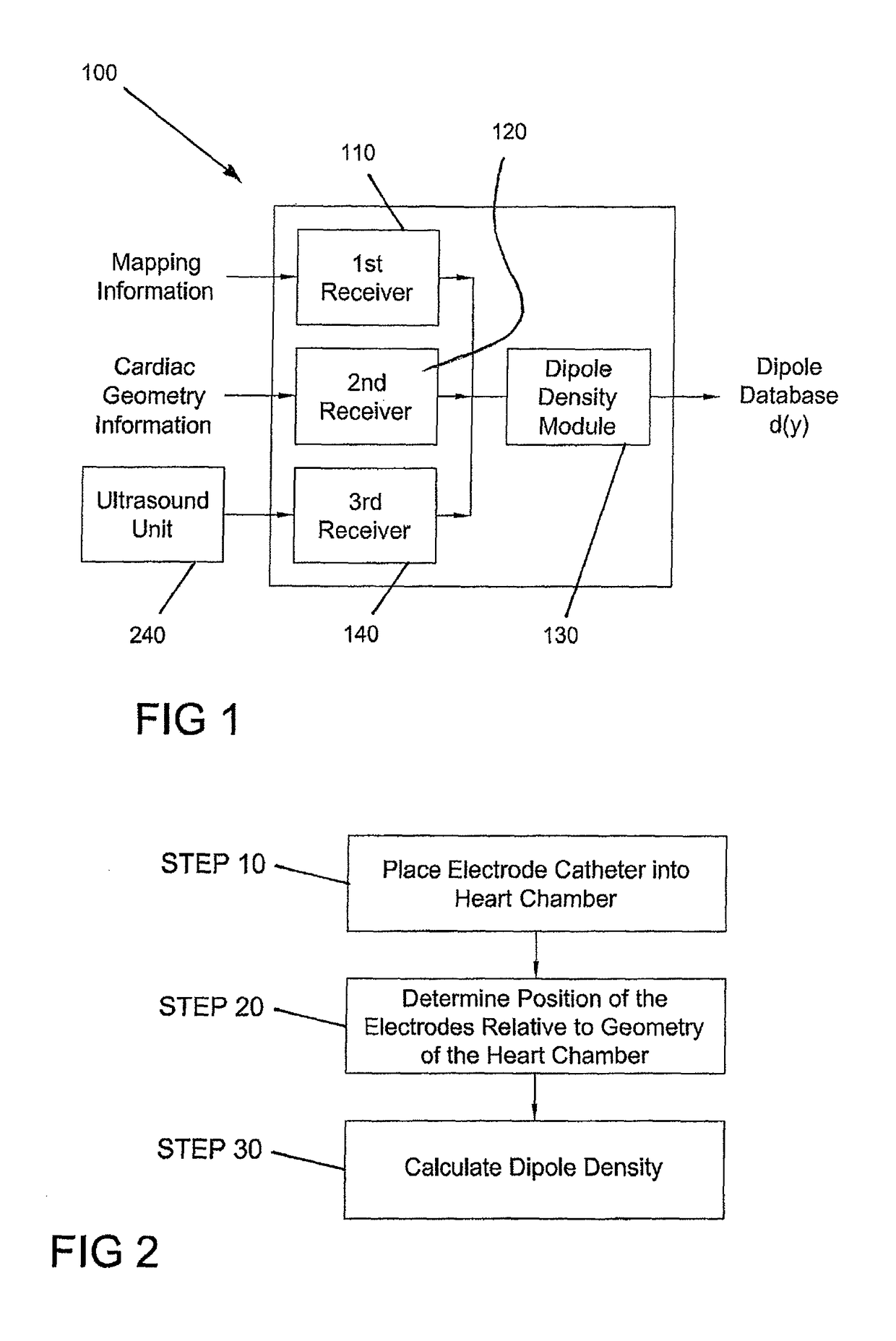
Disclosed are devices (100), systems (500), and methods for determining the dipole densities on heart walls. In particular, a triangularization of the heart wall is performed in which the dipole density of each of multiple regions correlate to the potential measured at various located within the associated chamber of the heart. To create a database of dipole densities, mapping information recorded by multiple electrodes (316) located on one or more catheters (310) and anatomical information is used. In addition, skin electrodes may be implemented. Additionally, one or more ultrasound elements (340) are provided, such as on a clamp assembly or integral to a mapping electrode, to produce real time images of device components and surrounding structures.

Description

FIELD OF THE INVENTION[0001]The present invention relates generally to the localization and treatment of cardiac arrhythmias, and more particularly to devices and methods for real time, non-contact imaging and distance measurements using ultrasound for dipole density mapping, as well as methods for diagnosing tissue health.BACKGROUND OF THE INVENTION[0002]Systems used to localize the origin of cardiac arrhythmias measure potentials (e.g. in millivolts) in the cardiac chambers and localize them on a three dimensional representation of the cardiac chamber wall. The measurement of the electrical activity present on the cardiac walls is called mapping. For this purpose, a multiple electrode mapping catheter may be positioned within the heart such that multiple potentials can be simultaneously measured at different locations on the wall of the cardiac chamber without having direct wall contact (non-contact mapping). The cardiac chamber is visualized as a three dimensional structure, eith...

Claims


Application Information

Patent Timeline
Patent Type & Authority Patents(United States)
IPC IPC(8): A61B5/00A61B5/04A61B18/14A61B8/00A61B8/08A61B8/12A61B5/042A61B5/0205A61B5/06A61B5/308A61B5/296
CPCA61B5/04012A61B5/0422A61B5/4836A61B5/6858A61B5/0205A61B8/0841A61B8/0883A61B8/12A61B8/445A61B8/4483A61B8/5207A61B18/1492A61B5/065A61B5/6869A61B2562/0204A61B2562/0209A61B2576/023G16H30/40A61B5/0036A61B5/287A61B5/367
Inventor SCHARFSCHARF, GUNTERWERNETH, RANDELL L.
Owner ACUTUS MEDICAL INC
Why Eureka
Try Eureka