
Data center heat removal systems and methods

a data center and heat removal technology, applied in the field of data centers, can solve the problems of data center energy consumption, and a major cost consideration, and achieve the effects of minimizing the use of energy for air distribution, maximizing the air pressure differential, and efficiently managing the clima

Active Publication Date: 2017-09-19
LEFEBVRE DALE +1
View PDF45 Cites 11 Cited by
  • Summary
  • Abstract
  • Description
  • Claims
  • Application Information

AI Technical Summary

Benefits of technology

[0009]In some embodiments, these components are interchangeable and modular and are the basis of a novel solution that provides an efficient method of removing heat from a data center.
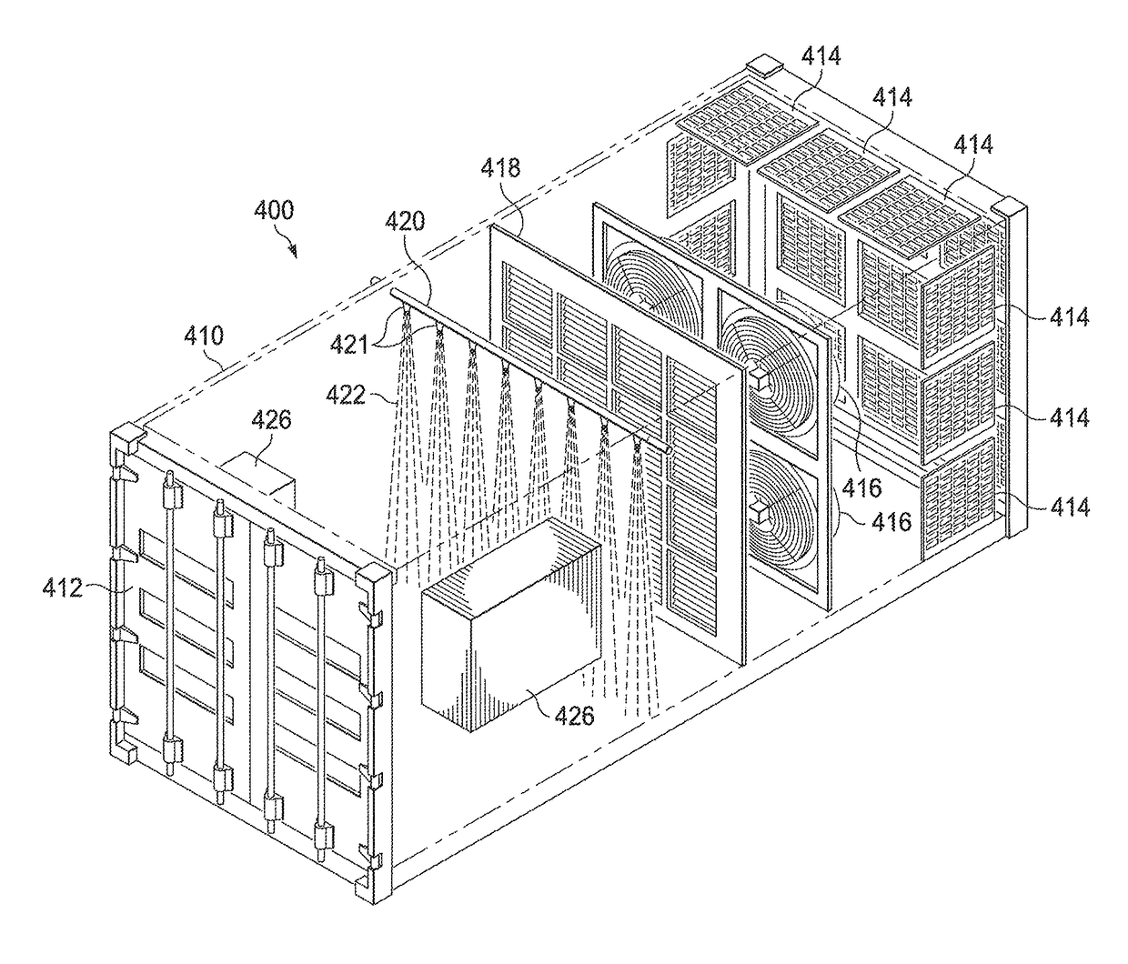
[0010]Embodiments utilize natural convection for heat removal from a data center including using the pressure differential between a hot aisle and a cold aisle. Embodiments may also use cold air from misters and / or freezer boxes for the intake of cold air. Some embodiments may use a natural process to form two distinct pressure regions in the data center. Some embodiments may use natural processes to maximize the air pressure differential between the cold aisle input of an individual server and its output to the warm aisle. Some embodiments allow natural process-driven multi-stage air cooling.
[0011]Advantageously, embodiments efficiently manage the climate (which can include temperature, humidity, air flow, and air quality, etc.) within a data center and minimize the use for energy for air distribution. Some embodiments minimize the use of active heat management equipment that generates heat through their own operation. Some embodiments minimize and eliminate the use of moving cooling parts. Some embodiments minimize maintenance costs associated with server heating and cooling. Some embodiments manage the costs of computing services.

Problems solved by technology

As such, energy usage consumed by data centers is a major cost consideration.
Energy costs in data centers arise from computing, networking activities, and power transformations that use energy and, as a byproduct, generate heat.
However, a majority of energy costs is associated with the removal of heat from the data center.
Active heat management equipment (i.e., air conditioning systems) is substantially less than 100% efficient, which means heat monitoring and management equipment adds to the data center heat removal problems because they generate heat through their own operation.

Method used


Image

  • Data center heat removal systems and methods
  • Data center heat removal systems and methods
  • Data center heat removal systems and methods

Examples


Embodiment Construction

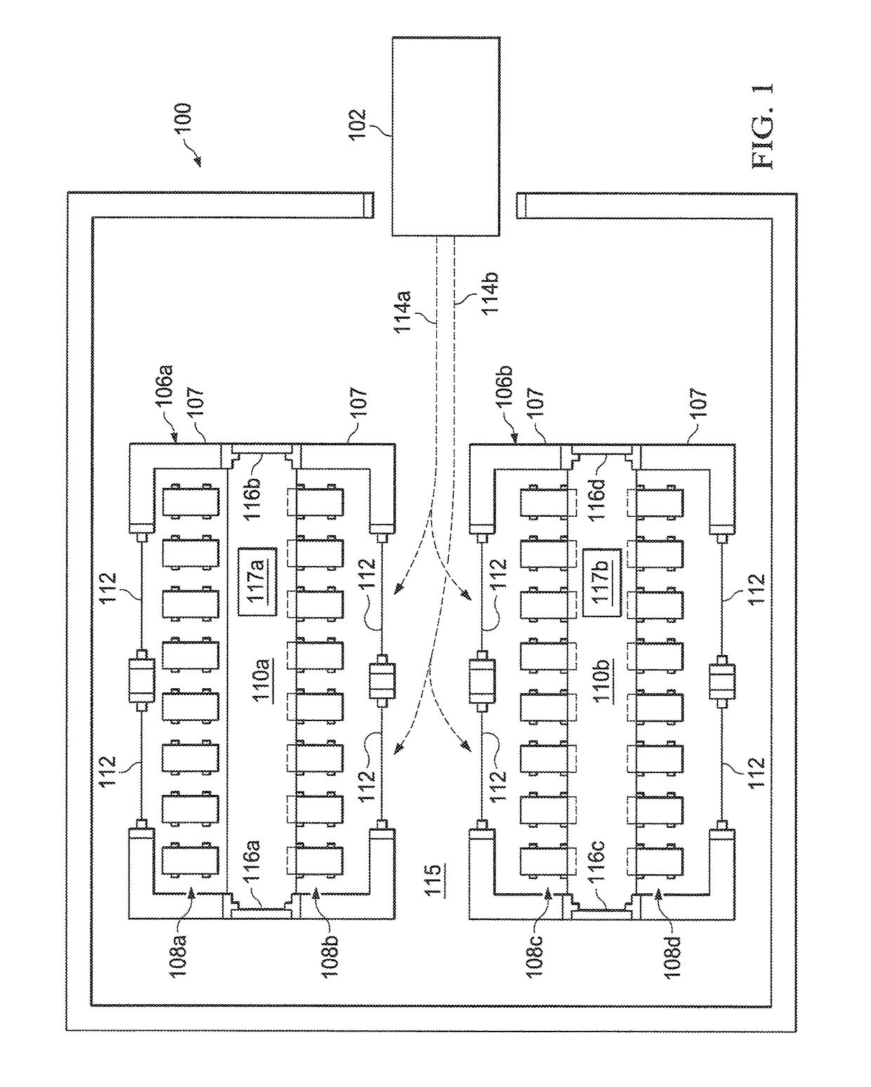
[0022]Following is a description of one exemplary data center environment in which a heat removal system may be implemented according to some embodiments. FIG. 1 depicts a diagram schematically illustrating a layout of a data center heat removal system according to some embodiments. In the example of FIG. 1, a data center heat removal system for a data center 100 includes a chilling unit 102. As will be described in greater detail below, the chilling unit 102 may include a housing, one or more fans or similar devices configured for drawing in air from outside the data center, one or more misters for cooling the air, and one or more chiller units for further reducing the air temperature.

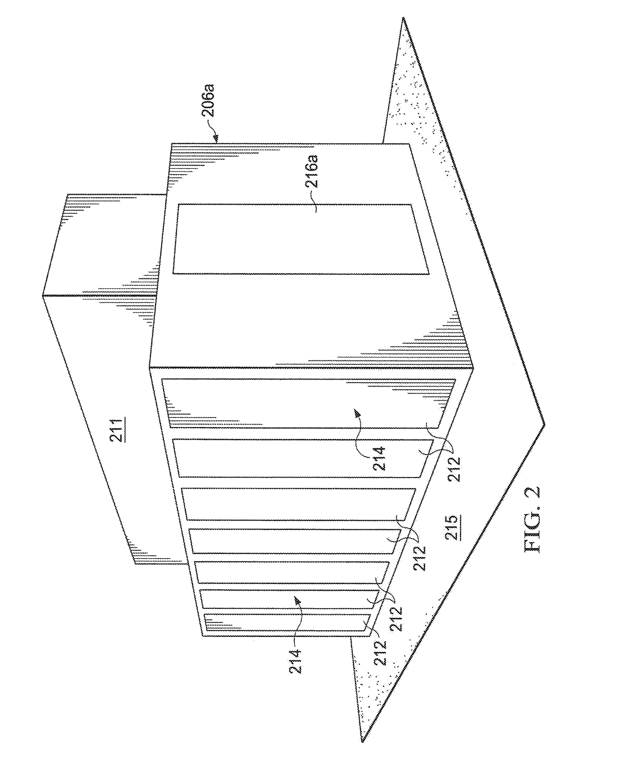
[0023]The data center 100 may include one or more server pods 106a and 106b. The server pods 106a and 106b may be embodied as self-contained rooms or enclosures that have walls 107, doors 116a, 116b, 116c, 116d, and ceilings (not shown). The server pods 106a and 106b are configured to house one or mor...


PUM


Abstract

New data center heat removal systems and methods allow a combination of active and passive thermal processes for removing heat from and cooling air in data center environments. Systems and methods include a data center heat removal system including an adjustable thermal feed cold air intake system, a distribution system for cold and warm air including one or more hot aisles and one or more cold aisles, and a convection system to draw cool air through data center equipment using a naturally-occurring convection processes to expel hot air. Misters, cooling elements, and / or freezer boxes may further cool the intake of air. A controller is programmed to efficiently manage and control the climate (e.g., temperature, humidity, air flow, pressure, air quality, etc.) within a data center to minimize the use for energy for air distribution and cooling.

Description

CROSS-REFERENCE TO RELATED APPLICATION(S)[0001]This is a conversion of, and claims a benefit of priority under 35 U.S.C. §119 from Provisional Application No. 62 / 098,176, entitled “DATA CENTER HEAT REMOVAL SYSTEMS AND METHODS,” filed Dec. 30, 2014, which is hereby fully incorporated by reference in its entirety, including appendices.COPYRIGHT NOTICE[0002]A portion of the disclosure of this patent document contains material which is subject to copyright protection. The copyright owner has no objection to the facsimile reproduction by any one of the patent document or the patent disclosure, as it appears in the Patent and Trademark Office patent file or records, but otherwise reserves all copyright rights whatsoever.TECHNICAL FIELD[0003]This disclosure relates generally to data centers. More particularly, this disclosure relates to new, improved systems and methods for cooling data center servers and removal of heat from data centers.BACKGROUND[0004]A data center is a facility used to...

Claims


Application Information

Patent Timeline
Patent Type & Authority Patents(United States)
IPC IPC(8): H05K7/20
CPCH05K7/20745H05K7/20827H05K7/20836
Inventor LEFEBVRE, DALECHOI, KENNETH
Owner LEFEBVRE DALE
Learn More