Unlock instant, AI-driven research and patent intelligence for your innovation.

Power output circuit and related control method

a power output circuit and output circuit technology, applied in the direction of generating/distributing signals, apparatus without intermediate ac conversion, etc., can solve the problems of parasitic capacitors consuming too much power, and extremely low operating efficiency

Active Publication Date: 2017-10-10
SITRONIX TECH CORP
View PDF7 Cites 0 Cited by
  • Summary
  • Abstract
  • Description
  • Claims
  • Application Information

AI Technical Summary

Benefits of technology

The present invention provides a control method to adjust the operating frequency of a charge pump in a power output circuit. This allows the charge pump to operate at an optimal frequency based on the load being driven.

Problems solved by technology

In addition, the built-in capacitor may always be accompanied by larger parasitic capacitors, and the excessively high frequency of the clock signal may cause that there is too much power consumed by the parasitic capacitors.
Especially when the load is light, the excessively high frequency may result in an extremely low operating efficiency.
In such a condition, if the frequency of the clock signal is too high, the parasitic capacitors may consume too much power, and if the frequency of the clock signal is too low, the driving capability of the output terminal may not be enough to immediately react to load variations.
These fixed frequencies cannot be adapted to any loading situations.
In such a situation, the output voltage may fluctuate around the threshold value, and the operating frequency may be continuously switched between the first frequency and the second frequency, resulting in poor system stability.
Moreover, the frequency is switched after a variation on the output voltage is detected, such that the output voltage inevitably possesses a certain level of fluctuation.
If the load varies significantly, it is hard to maintain a stable output voltage.
In such a condition, the prior art is only applicable to a circuit system having capacitive loads only, and cannot be applied to a circuit system having a larger resistive load.
This is because the resistive load has a larger variation, which easily causes the output voltage instable.

Method used


Image

  • Power output circuit and related control method
  • Power output circuit and related control method
  • Power output circuit and related control method

Examples


Embodiment Construction

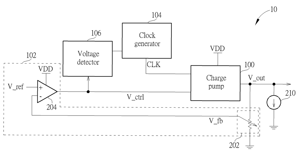
[0018]Please refer to FIG. 1, which is a schematic diagram of a power output circuit 10 according to an embodiment of the present invention. As shown in FIG. 1, the power output circuit 10 includes a charge pump 100, a voltage regulator 102, a clock generator 104 and a voltage detector 106. The charge pump 100 is used for receiving a clock signal CLK having an operating frequency and outputting an output voltage V_out. In detail, the charge pump 100 may include multiple capacitors, which are switched between different phases via the control of the clock signal CLK, in order to provide the electric charges in different capacitors for the load of the output terminal in different phases. The voltage regulator 102, coupled to the charge pump 100, may output a control voltage V_ctrl to the charge pump 100, to control the output voltage V_out. In detail, when the power output circuit 10 is launched, the power output circuit 10 may control the output voltage V_out to rise to a predetermine...


PUM


Abstract

A power output circuit includes a charge pump, a voltage regulator, a clock generator and a voltage detector. The charge pump is used for receiving a clock signal having an operating frequency and outputting an output voltage. The voltage regulator, coupled to the charge pump, is used for outputting a control voltage to the charge pump, to control the output voltage. The clock generator, coupled to the charge pump, is used for outputting the clock signal to the charge pump. The voltage detector, coupled to the clock generator and the voltage regulator, is used for detecting the control voltage and controlling the clock generator to adjust the operating frequency of the clock signal according to a magnitude of the control voltage.

Description

CROSS REFERENCE TO RELATED APPLICATIONS[0001]This application claims the benefit of U.S. Provisional Application No. 62 / 265,968, filed on Dec. 10, 2015, the contents of which are incorporated herein by reference.BACKGROUND OF THE INVENTION[0002]1. Field of the Invention[0003]The present invention relates to a power output circuit and a related control method, and more particularly, to a control method capable of adjusting an operating frequency of a charge pump in a power output circuit.[0004]2. Description of the Prior Art[0005]A charge pump, which is a common power supply circuit, may generate and output a voltage value higher than its input voltage. The voltage outputted by a charge pump may be of any magnification. For example, the input voltage may be multiplied by 2 or 3 and then outputted. If the charge pump is connected to a voltage regulator via a feedback circuit, the reference voltage in the voltage regulator may be used to realize a predetermined and stable output voltag...

Claims


Application Information

Patent Timeline
Patent Type & Authority Patents(United States)
IPC IPC(8): G06F1/10H02M3/07
CPCH02M3/07
Inventor CHENG, CHIA-CHI
Owner SITRONIX TECH CORP