Primary current sensing method for isolated LED driver

a technology of led driver and current sensing method, which is applied in the direction of electric variable regulation, process and machine control, instruments, etc., can solve the problem of costly conventional sensing techniques on the secondary sid

Active Publication Date: 2017-10-10
UNIVERSAL LIGHTING TECHNOLOGIES
View PDF6 Cites 13 Cited by
  • Summary
  • Abstract
  • Description
  • Claims
  • Application Information

AI Technical Summary

Benefits of technology

[0025]In certain embodiments, the DC-to-AC inverter includes a switch controller that controls the frequency of the primary AC voltage. The switch controller receives a reference signal having a value corresponding to a desired sensed primary current through the primary winding. The switch controller compares the value of the reference signal with an internal signal responsive to the feedback value and adjusts the frequency of the primary AC voltage to reduce any difference between the internal signal and the value of the reference signal. In certain embodiment...

Problems solved by technology

The isolation requirement causes conventional sensing techniques in the secondary side to be c...

Method used


Image

  • Primary current sensing method for isolated LED driver
  • Primary current sensing method for isolated LED driver
  • Primary current sensing method for isolated LED driver

Examples


Embodiment Construction

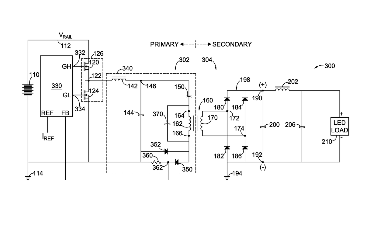
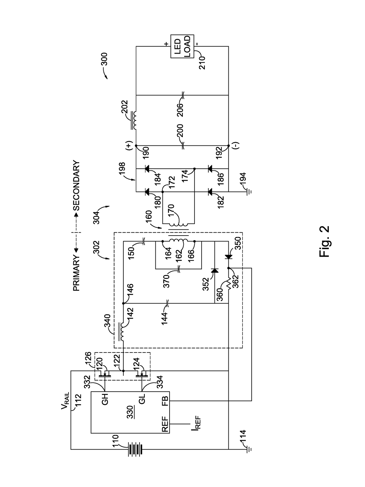
[0038]An exemplary solution to the problem disclosed in FIG. 1 is illustrated by an improved LED driver circuit 300 in FIG. 2. The LED driver circuit in FIG. 2 is similar in many aspects to the LED drive circuit 100 in FIG. 1 and corresponding components are numbered accordingly. The basic forward operational characteristics of a DC-AC inverter 302 on the primary side of the isolation transformer 160 and an AC-DC converter 304 on the secondary side of the transformer are similar to the previously described operational characteristics. Accordingly, the basic operation is not described again.

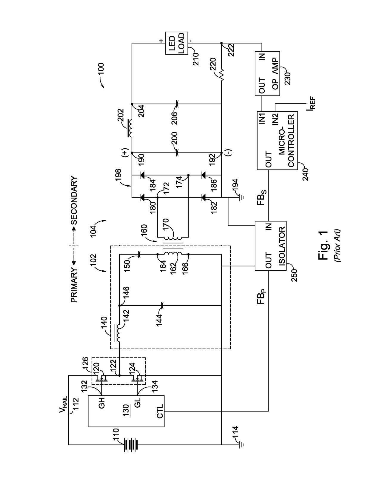
[0039]Unlike the previously described LED driver circuit 100 of FIG. 1, the improved LED driver circuit 300 of FIG. 2 does not have a feedback circuit from the secondary side to the primary side. The current sensing resistor 220, the operational amplifier 230, the microcontroller 240 and the isolator circuit 250 of FIG. 1 are not required in the LED driver circuit of FIG. 2. In FIG. 2 the negative...


PUM


Abstract

A DC-to-AC inverter provides power to a DC-to-AC converter via an isolation transformer. The DC-to-AC converter drives a DC load. A sensing circuit on the primary side of the isolation transformer senses the current flowing through the primary winding of the transformer. A capacitor is connected across the primary winding in parallel with the magnetizing inductance of the primary winding to form a parallel L-C combination. The capacitance of the capacitor is selected with respect to the magnetizing inductance such that the parallel L-C combination resonates at a nominal steady-state operating frequency of the DC-to-AC inverter, which causes the current through the primary winding to be proportional to a current through the DC load. The current through the primary winding is sensed and provided as a feedback signal to the DC-to-AC inverter to cause the DC-to-AC inverter to adjust the operating frequency to maintain the current at a desired magnitude.

Description

CROSS-REFERENCES TO RELATED APPLICATIONS[0001]This application claims benefit of the following patent application which is hereby incorporated by reference: U.S. Provisional Application No. 62 / 212,931 filed Sep. 1, 2015, entitled “Primary Current Sensing Method for Isolated LED Driver”[0002]A portion of the disclosure of this patent document contains material that is subject to copyright protection. The copyright owner has no objection to the reproduction of the patent document or the patent disclosure, as it appears in the U.S. Patent and Trademark Office patent file or records, but otherwise reserves all copyright rights whatsoever.BACKGROUND OF THE INVENTION[0003]The usage of light-emitting diodes (LEDs) to provide illumination is increasing rapidly as the cost of LEDs decrease and the endurance of the LEDs increases to cause the overall effective cost of operating LED lighting products to be lower than incandescent lamps and fluorescent lamps providing equivalent illumination. A...

Claims


Application Information

Patent Timeline
IPC IPC(8): H02M3/335H02M1/08H05B33/08H02M1/00H05B44/00
CPCH02M3/33507H05B33/0815H02M1/08H02M2001/0009H02M3/3376Y02B70/10H05B45/382H02M1/0009
Inventor XIONG, WEIUNGACTA, CANDICE
Owner UNIVERSAL LIGHTING TECHNOLOGIES
Why Eureka
Try Eureka