Measuring device for reflection measurements of test objects and method for measuring radiation reflected by test objects

a technology of reflection measurement and test object, which is applied in the direction of material instruments, and solids analysis using sonic/ultrasonic/infrasonic waves. it can solve the problems of small signal-to-noise ratio, less flexibility and complicated design, and achieve simple and flexible design

Active Publication Date: 2017-10-17
INOEX
View PDF9 Cites 5 Cited by
  • Summary
  • Abstract
  • Description
  • Claims
  • Application Information

AI Technical Summary

Benefits of technology

[0006]The object of the invention, therefore, is to provide a measuring device for reflection measurements of test objects, which has a simple, flexible design and is adaptable to the test object.
[0007]This object is achieved by a measuring device having the features of Claim 1. As a result of at least two of the elements from the group which comprise the first collimation element, the first focusing element, the second collimation element, and the second focusing element being separate from one another, the measuring device may have a simple, flexible design and may be adapted to the test object or to the available installation space. Individual elements may be easily changed, depending on the test object, so that the signal quality and / or the required installation space may be optimized. The transmitter and the receiver are separate, so that the receiver is optimally adaptable to the reflected radiation and an optimal signal quality of the measured radiation achieved. The emitted radiation and / or reflected radiation have / has in particular a frequency in the range of 0.01 THz to 50 THz, in particular 0.05 THz to 20 THz, and in particular 0.1 THz to 5 THz.
[0008]A measuring device according to Claim 2 allows a comparatively compact design. As a result of the transmitter and the receiver being situated in succession or one behind the other along the beam direction, i.e., along an optical axis, the transmitter and the receiver may be situated in an overlapping manner. A compact design is achieved in this way. In particular, the first collimation element and the second focusing element are also separate from one another. The first collimation element and the second focusing element may thus be situated in an offset manner along the beam direction and / or designed with different focal lengths.

Problems solved by technology

However, a disadvantage of reflection measurements is the small signal-to-noise ratio, since for measurements of test objects made of plastics, for example, the reflectance is lower than the transmittance.
A disadvantage of the known measuring device is that it has a less flexible and complicated design.

Method used


Image

  • Measuring device for reflection measurements of test objects and method for measuring radiation reflected by test objects
  • Measuring device for reflection measurements of test objects and method for measuring radiation reflected by test objects
  • Measuring device for reflection measurements of test objects and method for measuring radiation reflected by test objects

Examples


first embodiment

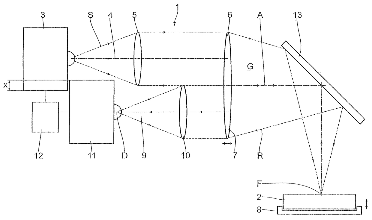
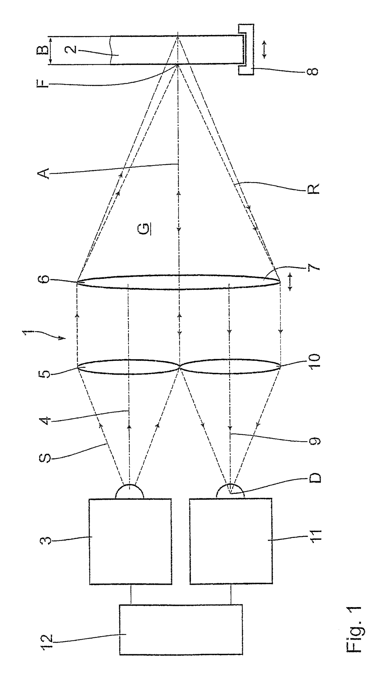
[0030]the invention is described below with reference to FIG. 1. A measuring device 1 is used for carrying out reflection measurements of a test object 2. For this purpose, the measuring device 1 has a transmitter 3 which emits radiation having a frequency in the range of 0.01 THz to 50 THz, in particular 0.05 THz to 20 THz, and in particular 0.1 THz to 5 THz. The transmitter 3 or the transmitting antenna has a customary design, and emits the radiation in a cone shape in a beam direction 4. The emitted radiation is denoted by reference character S in FIG. 1. The beam direction 4 defines an optical axis of the transmitter 3.

[0031]A first collimation element 5 is situated downstream from the transmitter 3 in the beam direction 4. The first collimation element 5 is designed as a convex lens. The convex lens 5 is situated concentrically with respect to the optical axis of the transmitter 3 or of the radiation cone of the emitted radiation S. The first collimation element 5 is used for t...

third embodiment

[0045]the invention is described below with reference to FIG. 3. In contrast to the preceding embodiments, the measuring device 1 has a deflection element 13 situated in the beam path between the first focusing element 6 and the test object 2 or the test object holder 8, and between the test object 2 or the test object holder 8 and the second collimation element 7. The space between the first focusing element 6 or the second collimation element 7 and the deflection element 13, and between the deflection element 13 and the test object holder 8, is filled with a gas G, in particular with air, corresponding to the preceding embodiments. The deflection element 13 is designed as a mirror which in particular is planar. An arrangement of the test object 2 at a distance from or transversely with respect to the optical axis A is made possible by the deflection element 13. The measuring device 1 is thus easily and flexibly adaptable to the test object 2 or a given installation space. With reg...

fourth embodiment

[0046]the invention is described below with reference to FIG. 4. In contrast to the preceding embodiments, the first focusing element 6 and the second collimation element 7 are designed in one piece as a mirror. The mirror has a parabolic shape, so that the emitted radiation S is focused and the reflected radiation R is collimated. In addition, the mirror 6 or 7 also deflects the emitted radiation S or the reflected radiation R, respectively, and consequently acts as a deflection element. The space between the mirror 6 or 7 and the test object 2 or the test object holder 8 is filled with a gas G, in particular with air, corresponding to the preceding embodiments. With regard to the further design and the mode of operation of the measuring device 1, reference is made to the preceding embodiments.

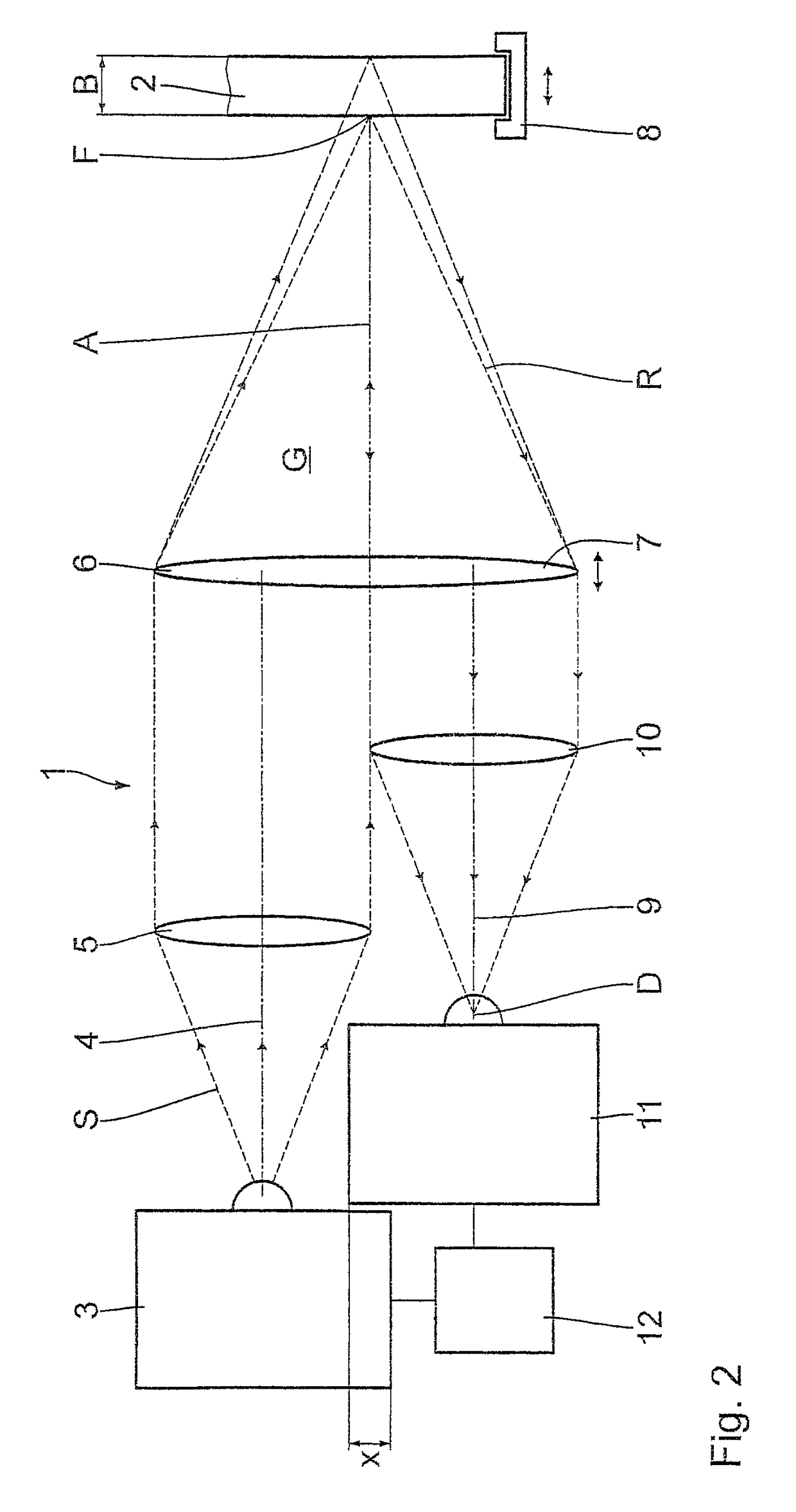
[0047]A fifth embodiment of the invention is described below with reference to FIG. 5. In contrast to the preceding embodiments, the first collimation element 5 and the second focusing elemen...


PUM

PropertyMeasurementUnit
reflection measurementsaaaaaaaaaa
thicknessaaaaaaaaaa
overlap areaaaaaaaaaaa

Abstract

A measuring device for reflection measurements of test objects includes a transmitter for emitting radiation, a first collimation element for aligning the emitted radiation, a first focusing element for focusing emitted radiation in relation to the test object, and a receiver for detecting radiation reflected by the test object. There is a second collimation element for aligning the reflected radiation, and a second focusing element for focusing the reflected radiation in relation to the receiver. At least two of the first and second collimation elements and first and second focusing elements are separate from each other. Thus, a simple and flexible design of the measuring device is achieved, which can be adapted to the test object.

Description

CROSS-REFERENCE TO RELATED APPLICATIONS[0001]This application is a continuation of Application No. PCT / DE2014 / 100304, filed 26 Aug. 2014, which claims the priority of German Patent Application No. 10 2013 217 038.6, filed 27 Aug. 2013, and each of which is incorporated herein by reference.FIELD OF THE INVENTION[0002]The present invention relates to a measuring device for reflection measurements of test objects, and method for measuring radiation reflected on test objects.[0003]The invention relates to a measuring device for reflection measurements of test objects according to the preamble of Claim 1. The invention further relates to a method for measuring radiation reflected on test objects. The radiation used for the measurement is in particular terahertz radiation.BACKGROUND OF THE INVENTION[0004]Reflection measurements of test objects are carried out, for example, to determine the wall thickness of the test objects. Compared to transmission measurements, reflection measurements h...

Claims


Application Information

Patent Timeline
Patent Type & Authority Patents(United States)
IPC IPC(8): G01B11/06G01N29/04G01N21/3581G01N21/55G01N29/22
CPCG01B11/06G01N21/3581G01N21/55G01N29/04G01N29/221G01N2291/02854
Inventor HOCHREIN, THOMAS
Owner INOEX
Why Eureka
Try Eureka