Drive mechanism for rotatably coupling a system part or a machine part

a technology of rotatably coupling and system parts, applied in the direction of mechanical energy handling, mechanical apparatus, roller bearings, etc., can solve the problems of reducing the number of external parts, and achieve the effect of improving synchronization, reducing the number of coils, and improving the synchronization

Active Publication Date: 2017-10-17
IMO HOLDING GMBH
View PDF12 Cites 2 Cited by
  • Summary
  • Abstract
  • Description
  • Claims
  • Application Information

AI Technical Summary

Benefits of technology

[0040]A plurality of coils should be connected in series to form one or more strings. This has the advantage that all the coils in a string are traversed by a current of the same amplitude, and thus exactly the same magnetization is induced. The drive power is therefore distributed evenly over all the coils in a string.
[0041]The invention prefers that three strings of coils be provided, corresponding to a three-phase current system. In the case of excitation with currents having a sinusoidal amplitude and an electrical offset between two phases of 120° or 240°, respectively, a three-phase current system has the advantage of a power flow that is completely constant over time. In the context of the invention, this has a favorable effect on the synchronization properties of a rolling bearing driven in this manner.
[0042]It is possible for each string to have 10 coils or more connected in series, for example respectively 20 coils or more, preferably 30 coils or more, particularly 40 coils or more. The greater the number of coils, the better the synchronization. In the case of excitation at the same frequency, a multi- or even high-pole machine, though it runs more slowly than a single- or low-pole machine, can be regulated with much higher precision.

Problems solved by technology

A further consideration is the resulting decrease in the number of external parts, which might, for example, be damaged by collisions.

Method used


Image

  • Drive mechanism for rotatably coupling a system part or a machine part
  • Drive mechanism for rotatably coupling a system part or a machine part
  • Drive mechanism for rotatably coupling a system part or a machine part

Examples


Embodiment Construction

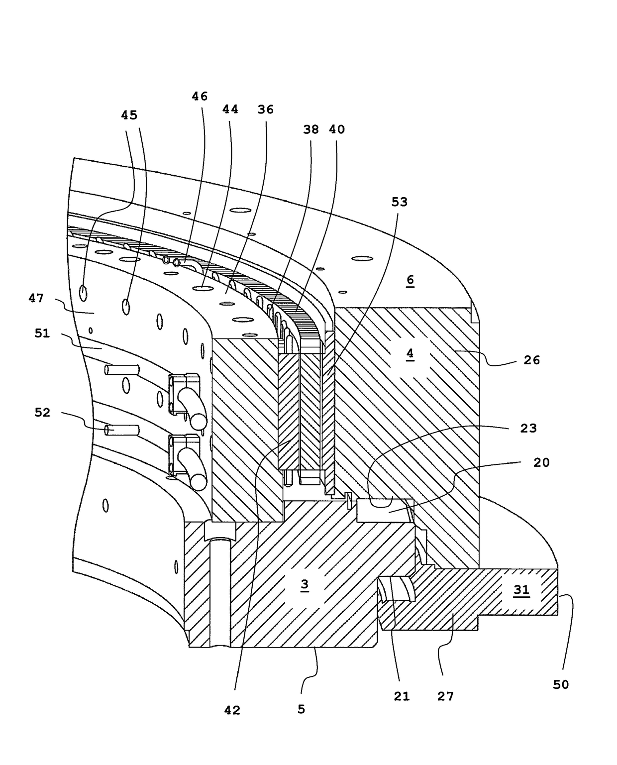
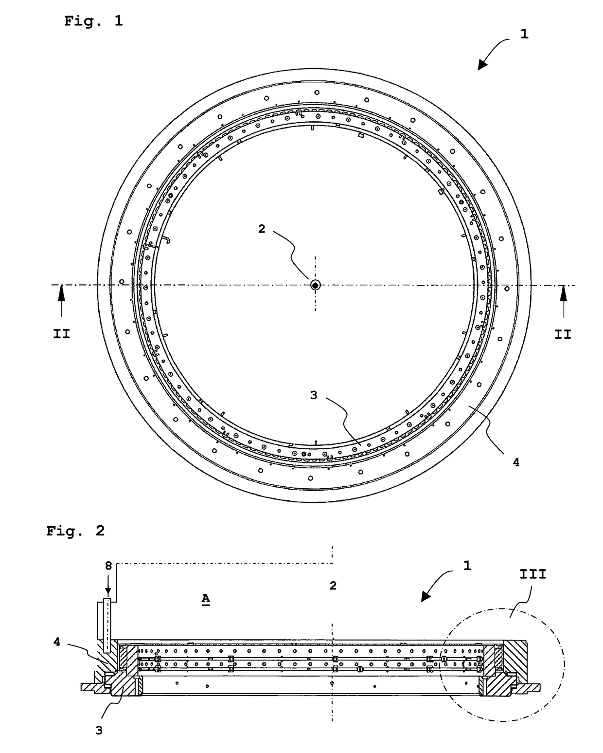
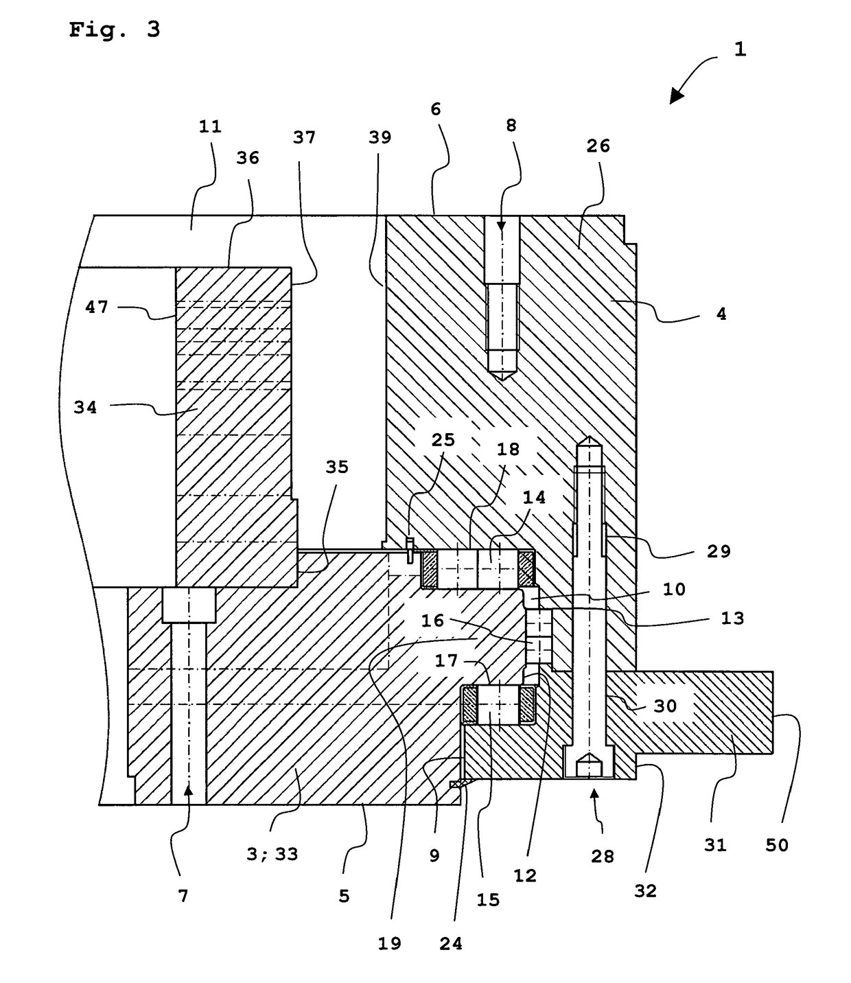
[0065]As can be appreciated from FIG. 1, the drive mechanism 1 according to the invention for rotatably coupling two system parts or machine parts or the like has a ring-shaped structure and is rotationally symmetrical to a center axis 2 of said ring structure.

[0066]An essential element of the drive mechanism 1 is two ring-shaped, substantially planar connecting elements 3, 4.

[0067]Each of these connecting elements 3, 4 is provided with at least one respective planar connecting surface 5, 6 together with fastening means 7, 8, arranged distributed in a crown shape therein and provided for connection to different system parts or machine parts or the like. These fastening means are preferably bores for receiving fastening screws, for example internally threaded blind bores or through-bores. The connecting surfaces 5, 6 of the two connecting elements 3, 4 are preferably located on oppositely disposed end sides of the drive mechanism 1, i.e., for example, one at the top and one at the bo...


PUM

PropertyMeasurementUnit
phase voltagesaaaaaaaaaa
contact angleaaaaaaaaaa

Abstract

The invention relates to a drive mechanism (1) for rotatably coupling a first system part or machine part, preferably an assembly (A), to a base, pedestal or frame or to another system part or machine part, for example for rotary positioning during the processing of large workpieces or during the moving of loads, which drive mechanism comprises two ring-shaped connecting elements (3, 4) each having at least one planar connecting surface (5, 6) and fastening means (7, 8) that are arranged distributed in a crown shape therein and effect connection to different system parts or machine parts or the like, said two connecting elements (3, 4) being arranged concentrically with each other and radially one inside the other with a gap-shaped interspace (9) in which are disposed one or more rows of rolling elements (14, 15, 16), each row whereof rolls between two respective raceways (17, 18) on the two connecting elements (3, 4), thus enabling same to rotate relative to each other, at least one connecting surface (5, 6) and at least one raceway (17, 18) being formed by machining or shaping a common base body. The invention is characterized in that at least one fully circumferentially extending row of magnets (40) is arranged inside the gap (9) on one connecting element (3, 4) and at least one fully circumferentially extending row of coils (38) is arranged directly opposite said magnets on the other connecting element (4, 3). According to the invention, at least one fully circumferentially extending row of magnets is arranged inside the gap on one connecting element and at least one fully circumferentially extending row of coils is arranged directly opposite said magnets on the other connecting element.

Description

REFERENCE TO PENDING PRIOR PATENT APPLICATIONS[0001]This patent application claims benefit of International (PCT) Patent Application No. PCT / DE2013 / 000448, filed 7 Aug. 2013 by IMO Holding GmbH for DRIVE MECHANISM FOR ROTATABLY COUPLING A SYSTEM PART OR A MACHINE PART, which claims benefit of German Patent Application No. DE 10 2012 025 600.0, filed 31 Dec. 2012, which patent applications are hereby incorporated herein by reference.FIELD OF THE INVENTION[0002]The invention relates to a drive mechanism for rotatably coupling a system part or a machine part to a base, pedestal or frame or to another system part or machine part, preferably for rotatably coupling two relatively rotatable parts of a heavy-duty vehicle or even a construction machine, alternatively for the rotary positioning of large workpieces, which drive mechanism comprises two ring-shaped connecting elements each having at least one planar connecting surface and fastening means arranged distributed in a crown shape for...

Claims


Application Information

Patent Timeline
Patent Type & Authority Patents(United States)
IPC IPC(8): H02K7/08H02K11/21F16C19/38H02K7/14H02K21/22F16C41/00H02K7/102E02F9/12B66C23/84H01F38/18
CPCH02K7/088B66C23/84E02F9/123F16C19/381F16C41/001F16C41/004H01F38/18H02K7/102H02K7/14H02K11/21H02K21/22F16C2300/02F16C2300/14F16C2322/39F16C2350/26
Inventor FRANK, HUBERTUSDIETZ, VOLKER
Owner IMO HOLDING GMBH
Why Eureka
Try Eureka