Circuit breaker with current limiting and high speed fault capability

a circuit breaker and current limit technology, applied in the field of circuit breaker, can solve the problems of damage to the electrical distribution system itself and the connected equipment, and increasing the amount of time the person is in the offi

Active Publication Date: 2017-10-24
CARLING TECH
View PDF10 Cites 2 Cited by
  • Summary
  • Abstract
  • Description
  • Claims
  • Application Information

AI Technical Summary

Benefits of technology

[0015]What is desired, therefore, is a circuit breaker that allows for very fast tripping for a relatively large current spike but would not trip for a relatively small current spike.
[0016]It is further desired to provide a circuit breaker that can very quickly open an electrical circuit with a high current surge but would not open for a small current spike the functioning that does not comprise an overly complicated design, needs frequent maintenance, and is compact in size and relatively low cost.
[0017]It is still further desired to provide a mechanism that assist the contacts to open more quickly than conventional contacts to as to avoid damage to any devices connected to the circuit in the event of a short or fault condition.
[0019]In particular, a linkage which acts as a spring mechanism, provides a mechanical advantage to assist the high speed solenoid to open the contacts in a very short period of time. The linkage, may comprise multiple pivot arms including, for example, a first pivot arm, a second pivot arm connected to the first pivot arm, and a third pivot arm connected to the second pivot arm. It will be understood that the first pivot arm may be connected to a handle and the third pivot arm may be connected to a moveable contact.
[0020]In the above-described linkage configuration, the linkage includes a mechanical advantage such that, when the contacts are in a closed position, an angle θ1 is formed between the first pivot arm and the second pivot arm, where the angle θ1 is less than 180 degrees. Additionally, when the contacts are in the open position, an angle θ3 is formed between the first pivot arm and the second pivot arm, wherein the angle θ3 is greater than 180 degrees. The mechanical advantage (spring mechanism) functions to open the contacts much more quickly than conventional switches because the linkage functions to mechanically snap the contacts open.

Problems solved by technology

However, this configuration is disadvantageous in that in the event of a relatively small over current for an extended period of time, the circuit breaker would not trip.
This is undesirable as it could lead to damage of the electrical distribution system itself and to equipment connected to the distribution system.
However, the introduction of the delay prevents the circuit breaker from immediately tripping when a dangerous high current spike or short, occurs, which can severely damage both the electrical distribution system itself and the connected equipment.
For example, in situation where a ground fault occurs, a person may accidentally come into contact with electrical current, which any delay in the tripping of the circuit breaker corresponds to an increase in the amount of time the person is in contact with the live electrical circuit leading to severe injury, or even death.
Likewise, during a short circuit condition, if the circuit breaker is delayed before tripping, the equipment connected to the electrical circuit may be severely damaged.
However, current limiting circuit breakers with a built-in time delay generally do not trip until after the angle θ of the sine wave reaches zero.
Accordingly, in one situation where a large current spike occurs just after the zero crossing, the delay in the breaker tripping can approach the time it takes for the sine wave to cycle 180°, which is unacceptable.
However, this configuration has the disadvantage of being bulky, requiring many complex components including an oil dash-pot, which may be subject to leaking.
The complex and numerous parts and required maintenance result in a relatively expensive device that is not appropriate for many installations.
A major disadvantage of the bi-metallic strip is that the rate of heating and cooling of the bi-metal is affected by ambient temperature, the performance of the breaker differs for different ambient temperatures.
While this major drawback can be addressed somewhat by use of a resistance temperature detector (RTD), this again leads to a complex device having numerous parts and requires a controller to control the RTD leading to a relatively expensive device and is simply not appropriate for many installations.
However, a limitation of the above-listed references relates to the speed at which the system can react to overcurrent conditions.

Method used


Image

  • Circuit breaker with current limiting and high speed fault capability
  • Circuit breaker with current limiting and high speed fault capability
  • Circuit breaker with current limiting and high speed fault capability

Examples


Embodiment Construction

[0035]The exemplary embodiments of the present invention may be further understood with reference to the following description and the related appended drawings, wherein like elements are provided with the same reference numerals.

[0036]The exemplary embodiments of the present invention are related to a device capable of opening an electrical circuit very rapidly in the event of a fault or overcurrent condition. Specifically, the device uses a multiple solenoids to open the contacts in a circuit breaker, each solenoid functioning differently such that the circuit breaker is adapted to properly function under multiple different conditions. The exemplary embodiments are described with reference to a circuit breaker, but those skilled in the art will understand that the present invention may be implemented on any electrical device that has electrical contacts that can be opened and closed.

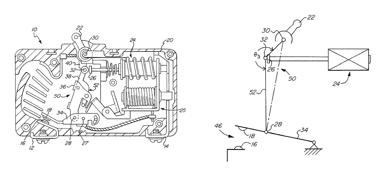
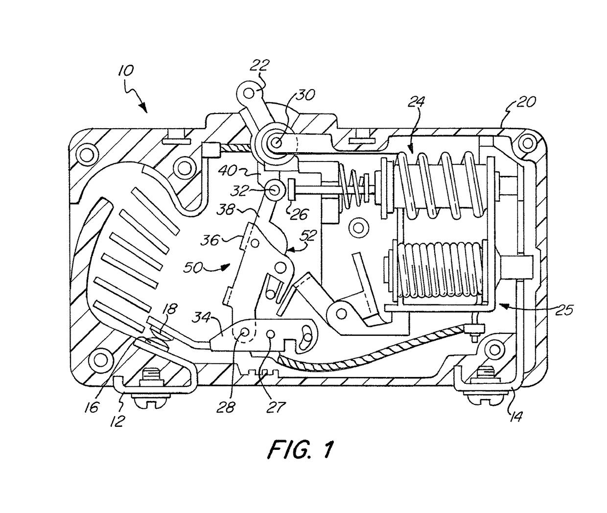
[0037]As best seen in FIG. 1 (FIG. 1), a circuit breaker 10 according to one embodiment of the pres...


PUM


Abstract

A circuit breaker arraignment includes at least two trip mechanisms. The first trip mechanism acts to immediately trip to open contacts of the circuit breaker upon reaching a first threshold current level, and the second trip mechanism acts to trip to open the contacts once both a second current threshold is reached and a time delay has elapsed. The contacts are moved by a linkage assembly that is held under mechanical advantage such that when acted on by one of the two trip mechanisms, the mechanical advantage is released to rapidly open the contacts.

Description

FIELD OF THE INVENTION[0001]The present invention relates generally to the protection of electrical devices, and more specifically, relates to a circuit breaker having a first high speed solenoid for interrupting a circuit at higher current faults and a second solenoid for interrupting a circuit at lower current faults.BACKGROUND OF THE INVENTION[0002]A circuit interrupter is an electrical component that can break an electrical circuit, interrupting the current. A basic example of a circuit interrupter is a switch, which generally consists of two electrical contacts in one of two states; either closed meaning the contacts are physically touching and electrical current pass from one contact to the other, or open, meaning the contacts are separated relative to each other thereby preventing the flow of electrical current there between. A switch may be directly manipulated by a person as a control signal to a system, such as a computer keyboard button, or to control power flow in a circ...

Claims


Application Information

Patent Timeline
Patent Type & Authority Patents(United States)
IPC IPC(8): H01H71/40H02H3/093H01H71/10
CPCH01H71/40H02H3/093H01H71/1009
Inventor FASANO, MICHAEL
Owner CARLING TECH
Why Eureka
Try Eureka