Over-current protection device

a protection device and overcurrent technology, applied in the direction of resistor manufacture, current responsive resistors, varistors, etc., can solve the problems of poor adhesion of ceramic powder to polyolefin polymer, easy accumulation of filler particles, and less uniform dispersion, etc., to achieve excellent low resistance, fast tripping, and low melting point

Inactive Publication Date: 2012-05-01
POLYTRONICS TECH
View PDF6 Cites 1 Cited by
  • Summary
  • Abstract
  • Description
  • Claims
  • Application Information

AI Technical Summary

Benefits of technology

[0008]The present invention provides an over-current protection device. By adding a conductive nickel filler, non-conductive metal nitride filler with certain particle size distribution, and at least one crystalline polymer with a low melting point, the over-current protection device exhibits excellent low resistance, fast tripping at a lower temperature, high voltage endurance and resistance repeatability.
[0010]In an embodiment, the metal foils have rough surfaces with nodules and physically and directly contact the PTC material layer. The nickel filler may be powder with a particle size distribution between 0.01 μm and 30 μm, and more preferably between 0.1 μm and 15 μm. The nickel filler exhibits a volume resistivity below 500 μΩ-cm and is dispersed in the crystalline polymers. The crystalline polymers may be selected from high-density polyethylene (HDPE), low-density polyethylene (LDPE), polypropylene, polyvinyl chlorine and polyvinyl fluoride. The PTC material layer has a crystalline polymer with a melting point below 115° C. to achieve the purpose of fast tripping ability at low temperatures.
[0013]Current low resistance (approximately 20 mΩ) PTC conductive material having nickel conductive fillers can withstand only 6 volts. Because the nickel particles exhibiting weak magnetism are not easily dispersed in the material, the unevenly dispersed nickel particles significantly reduce the voltage endurance capability. Moreover, strong accumulating behavior of nickel particles tremendously reduces the machining capability of polymers. As mentioned above, the addition of non-conductive metal nitride filler can efficiently increase the dispersion of the nickel particles, thereby increasing the voltage endurance and machining capabilities.
[0015]When the conventional PTC material reaches a volume resistivity below 0.1 Ω-cm, it usually cannot sustain voltage higher than 12V. To increase the voltage endurance, non-conductive metal nitride filler essentially including inorganic nitrogen compound is added to the PTC material, and the thickness of the PTC material layer is greater than 0.1 mm, so that the PTC material of low resistivity can significantly increase the endurance voltage. The addition of the inorganic compound (non-conductive metal nitride filler) to the PTC material layer can alter the trip jump value (i.e., R1 / Ri indicating the resistance repeatability) to below 3, where Ri is the initial resistance value and R1 is the resistance measured one hour later after returning to room temperature.
[0016]Since the PTC material layer exhibits extremely low resistivity, the area of the PTC chip (i.e., the PTC material layer required in the over-current protection device of the present invention) cut from the PTC material layer can be reduced to below 50 mm2 preferably below 30 mm2, and the PTC chip will still exhibit the property of low resistance. Accordingly, more PTC chips are produced from a single PTC material layer, and thus the cost is reduced.
[0017]The over-current protection device further comprises two metal electrode sheets, connected to the two metal foils by solder reflow or by spot welding to form an assembly. The shape of the assembly (the over-current protection device) is axial-leaded, radial-leaded, terminal, or surface-mounted. Also, the two metal foils or the two metal electrode sheets may connect to a power source to form a conductive circuit loop such that the over-current protection device protects the circuit when an over-current occurs.

Problems solved by technology

If the metal particles are used as the conductive fillers, their larger specific weight results in a less-uniform dispersion.
For example, nickel fillers exhibit weak magnetism, so the filler particles accumulate easily and are not easily dispersed.
Moreover, since the ceramic powder lacks a rough surface like carbon black and has no obvious chemical function groups, the ceramic powder exhibits poor adhesion with the polyolefin polymer, compared to the adhesion of the carbon black to the polyolefin polymer, and consequently, the resistance repeatability of the PTC conductive material is not well controlled.

Method used


Image

  • Over-current protection device
  • Over-current protection device
  • Over-current protection device

Examples


Embodiment Construction

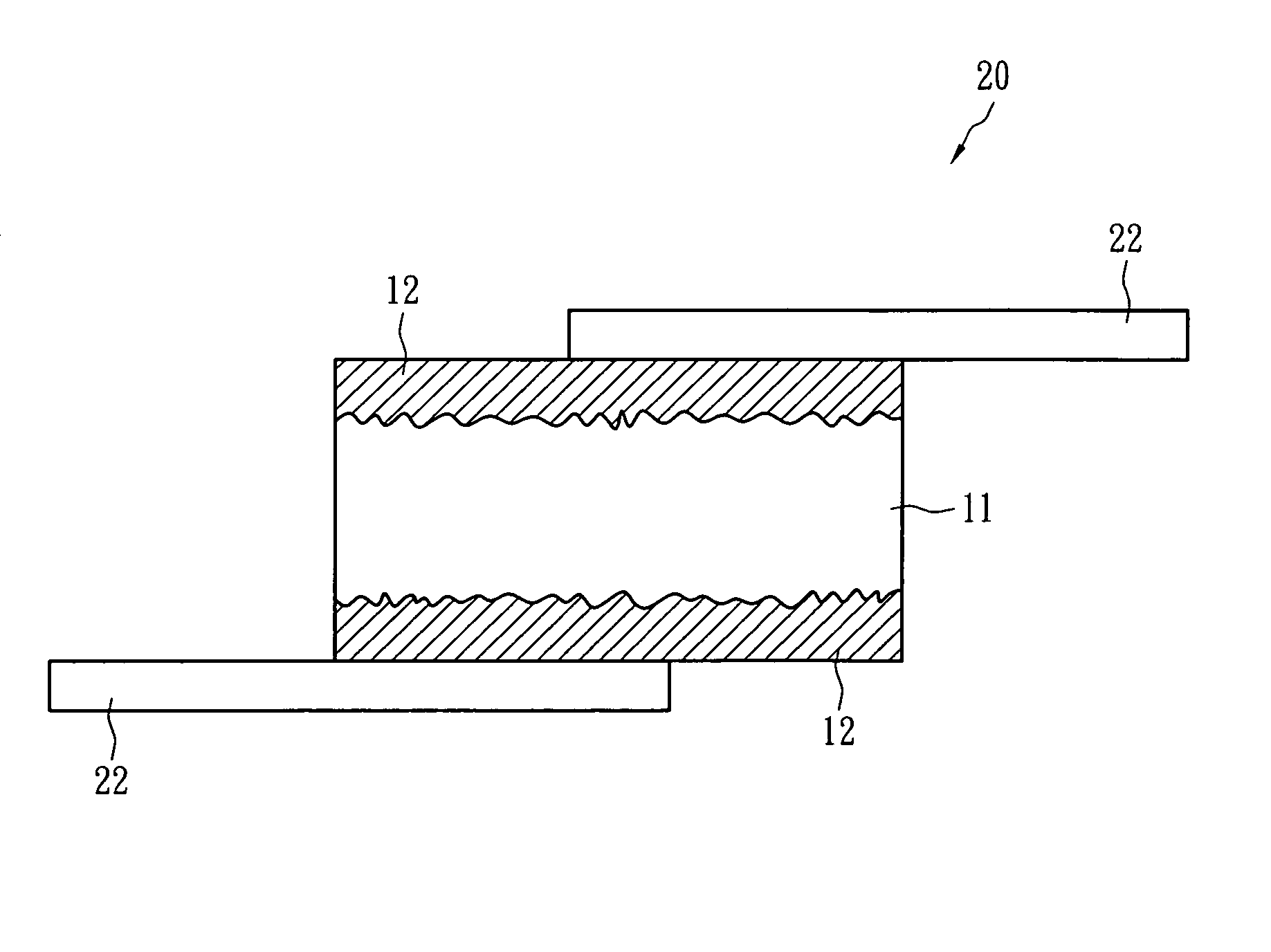
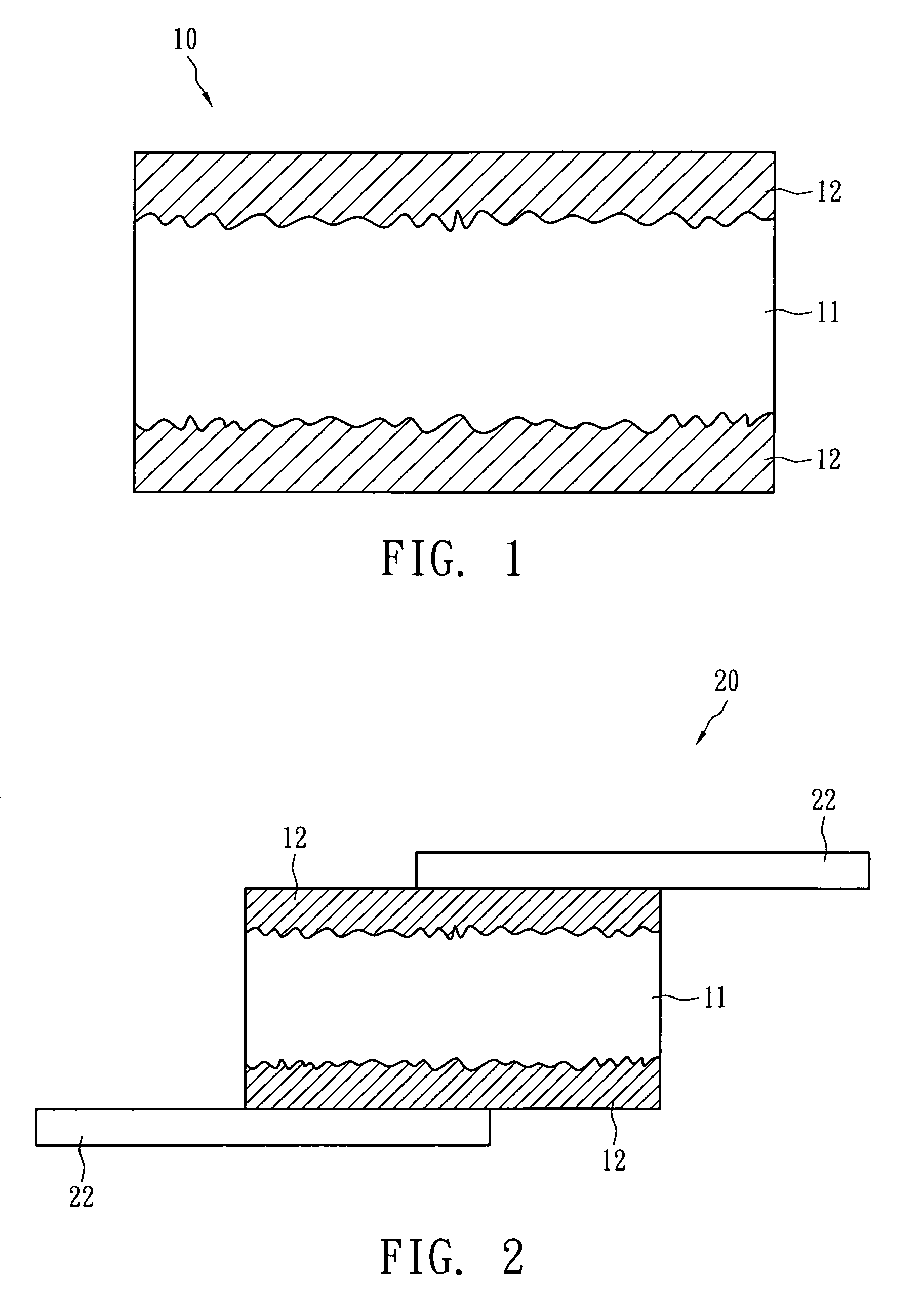
[0021]The following describes the compositions of Example I, Example II, Example III, Example IV, Comparative Example 1 and Comparative Example 2 and the manufacturing processes of the over-current protection device of the present invention with accompanying figures.

[0022]The composition and weight (unit in grams) of the PTC material layer in the over-current protection device of the present invention are shown in Table 1 below.

[0023]

TABLE 1LDPE-1HDPE-1HDPE-2BNAlNSi3N4Carbon BlackNiComposition(g)(g)(g)(g)(g)(g)(g)(g)Example I8.516.5—5———160Example II8.2—17.64.4———156Example III8.516.5——5.2——160Example IV8.2—17.6——5.4—160Comparative—8.110.2————150Example 1Comparative—9.29.73.6——33—Example 2

[0024]In Table 1, LDPE-1 is a low-density crystalline polyethylene (density: 0.924 g / cm3; melting point: 113° C.); HDPE-1 is a high-density polyethylene (density: 0.943 g / cm3; melting point: 125° C.); HDPE-2 is a high-density polyethylene (density: 0.961 g / cm3; melting point: 131° C.); boron nitrid...


PUM

PropertyMeasurementUnit
melting pointaaaaaaaaaa
particle sizeaaaaaaaaaa
thicknessaaaaaaaaaa

Abstract

An over-current protection device comprises two metal foils and a positive temperature coefficient (PTC) material layer. The PTC material layer is sandwiched between the two metal foils and has a volume resistivity below 0.1 Ω-cm. The PTC material layer includes (i) plural crystalline polymers having at least one crystalline polymer of a melting point less than 115° C.; (ii) an electrically conductive nickel filler having a volume resistivity less than 500 μΩ-cm; and (iii) a non-conductive metal nitride filler. The electrically conductive nickel filler and non-conductive metal nitride filler are dispersed in the crystalline polymer.

Description

BACKGROUND OF THE INVENTION[0001]1. Field of the Invention[0002]The present invention relates to an over-current protection device.[0003]2. Description of the Prior Art[0004]The resistance of PTC conductive material is sensitive to temperature change. Due to such property, the PTC conductive material can be used as current-sensing material and has been widely used in over-current protection devices and circuits. The resistance of the PTC conductive material remains low at room temperature so that the over-current protection device or circuit can operate normally. However, if an over-current or an over-temperature event occurs, the resistance of the PTC conductive material immediately increases to a high-resistance state (over 102 ohm). Therefore, the excessive current is blocked and the objective of protecting the circuit elements or batteries is achieved.[0005]In general, the PTC conductive material contains one or more crystalline polymers and a conductive filler. The conductive f...

Claims


Application Information

Patent Timeline
Patent Type & Authority Patents(United States)
IPC IPC(8): H01C7/10
CPCH01C7/027H01C17/06553H01C17/06586
Inventor SHA, YI ANLO, KUO CHANGCHU, FU HUA
Owner POLYTRONICS TECH
Why Eureka
Try Eureka