
Permanent magnet motor having reduced torque ripple

a permanent magnet motor and torque ripple technology, which is applied in the direction of dynamo-electric machines, dynamo-electric components, and dynamo-electric circuit shapes/forms/construction, etc., can solve the problems of large decrease in fundamental wave torque, limited application of stator slot skewing or rotor step skewing to concentrated winding with relatively few slots, etc., to reduce the sixth-harmonic torque, and reduce the overall torque rippl

Active Publication Date: 2017-10-31
ZHONGSHAN BROAD OCEAN
View PDF2 Cites 0 Cited by
  • Summary
  • Abstract
  • Description
  • Claims
  • Application Information

AI Technical Summary

Benefits of technology

The invention is a permanent magnet motor that reduces the torque ripple of its surface mounted permanent magnet rotor. The motor has a compact structure, small torque ripple, high fundamental wave torque, and smooth operation. It is easy to practice. The technical effects of the invention include the use of a rotor assembly with a plurality of permanent magnets and a rotor sheath separated into two segments to reduce torque ripple, which results in a back reaction that reduces torque ripple and prevents a decrease in fundamental torque. Additionally, the inner surface of the crown of each tooth portion is cut to form grooves to further decrease torque ripple. The use of a salient-pole surface mounted permanent magnet and a concentrated winding fractional slot design also contribute to the reduction of torque ripple and cost. The rotor sheath is made of magnetic and non-magnetic materials, making it compact and easy to select materials.

Problems solved by technology

However, the application of the stator slot skewing or the rotor step skewing is limited to concentrated winding with relatively few slots.
This is because the fewer the number of slots, the larger the axial misalignment angle that is required, which translates to a large decrease in the fundamental wave torque.

Method used


Image

  • Permanent magnet motor having reduced torque ripple
  • Permanent magnet motor having reduced torque ripple
  • Permanent magnet motor having reduced torque ripple

Examples


example 1

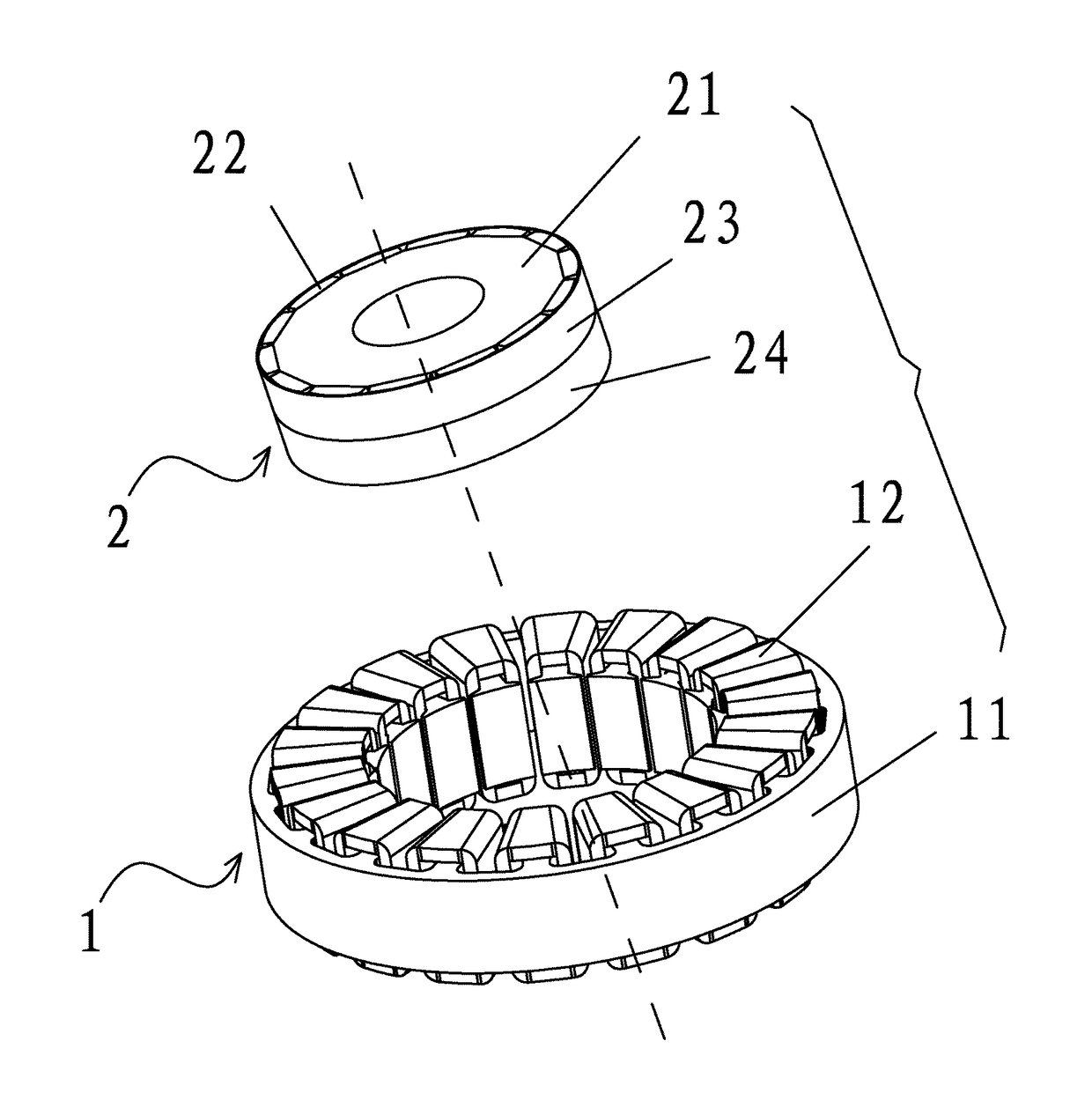
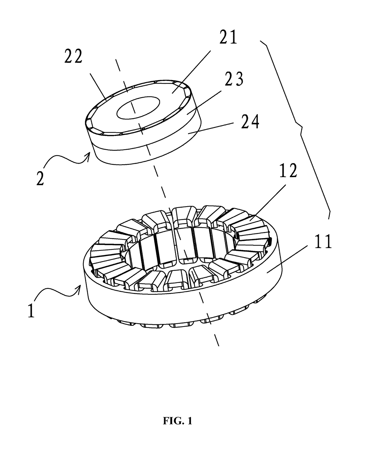
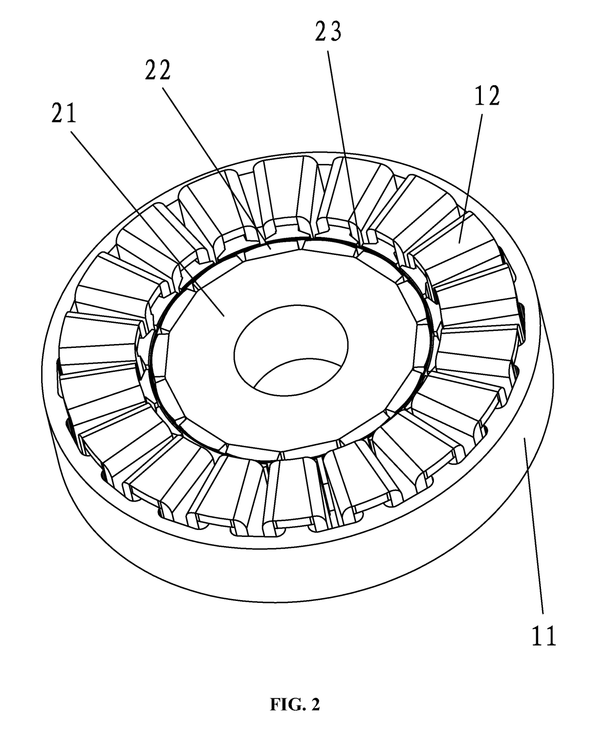
[0032]As shown in FIGS. 1-7, a permanent magnet motor adapted to reduce the torque ripple of a surface mounted permanent magnet rotor thereof, comprises: a stator assembly 1 and a rotor assembly 2. The stator assembly 1 comprises a stator core 11 and a coil winding 12. The stator core 11 comprises a yoke portion 111 and a plurality of tooth portions 112 extending out of the yoke portion. Winding slots 113 are formed between adjacent tooth portions 111. The rotor assembly 2 comprises a rotor core 21 and a plurality of permanent magnets 22 disposed on the surface thereof. The permanent magnets are disposed at intervals on a surface of the rotor core and magnetic poles of two facing sides of adjacent permanent magnets are the same. A rotor sheath is disposed outside the rotor assembly 2 and is divided into at least two segments axially. The magnetic conductivity of the first segment of the rotor sheath 23 is different from the magnetic conductivity of the second segment of the rotor sh...

example 2

[0033]As shown in FIG. 8, the example is an improvement of example 1, and the structure thereof is similar to that in example 1. The improvement is that: a rotor sheath is divided into three segments axially; and the magnetic conductivities of the first segment of the rotor sheath 23, the second segment of the rotor sheath 24, and the third segment of the rotor sheath 25 are different from one another and decrease respectively.

[0034]In the invention, the rotor sheath is divided into at least two segments axially; and the magnetic conductivity of the first segment of the rotor sheath 23 is different from the magnetic conductivity of the second segment of the rotor sheath 24, and the magnetic conductivities of different segments of the rotor sheath decrease in order. The rotor sheath features a compact structure and is easy to realize. Compared with a field in an air-gap performance and the sheath made of nonmagnetic materials, magnetic field of the sheath made of magnetic materials, ...


PUM


Abstract

A permanent magnet motor, including: a stator assembly and a rotor assembly. The stator assembly includes: a stator core and a coil winding. The stator core includes: a yoke portion, a plurality of tooth portions, and a plurality of winding slots. The rotor assembly includes: a rotor core, a plurality of permanent magnets, and a rotor sheath. The tooth portions are extended out of the yoke portion. Each winding slot is formed between adjacent tooth portions. The permanent magnets are disposed at intervals on a surface of the rotor core and magnetic poles of two facing sides of adjacent permanent magnets are the same. The rotor sheath is disposed outside the rotor assembly and is divided into at least two segments axially. A magnetic conductivity of a first segment of the rotor sheath is different from a magnetic conductivity of a second segment of the rotor sheath.

Description

CROSS-REFERENCE TO RELATED APPLICATIONS[0001]This application is a continuation-in-part of International Patent Application No. PCT / CN2014 / 073542 with an international filing date of Mar. 17, 2014, designating the United States, now pending, and further claims priority benefits to Chinese Patent Application No. 201320712610.5 filed Nov. 12, 2013. The contents of all of the aforementioned applications, including any intervening amendments thereto, are incorporated herein by reference. Inquiries from the public to applicants or assignees concerning this document or the related applications should be directed to: Matthias Scholl P.C., Attn.: Dr. Matthias Scholl Esq., 245 First Street, 18th Floor, and Cambridge, Mass. 02142.BACKGROUND OF THE INVENTION[0002]Field of the Invention[0003]The invention relates to a permanent magnet motor having reduced torque ripple.[0004]Description of the Related Art[0005]Typical measures to decrease torque ripple include: stator slot skewing, rotor step s...

Claims


Application Information

Patent Timeline
Patent Type & Authority Patents(United States)
IPC IPC(8): H02K29/03H02K1/26H02K1/16H02K1/08H02K1/27
CPCH02K29/03H02K1/08H02K1/16H02K1/26H02K1/278H02K1/2746H02K1/2773H02K1/274H02K2201/03
Inventor LIU, CHANGHONG
Owner ZHONGSHAN BROAD OCEAN
Learn More