
Thin film vascular stent and biocompatible surface treatment

a vascular stent and thin film technology, applied in the field of implantable devices, can solve the problems of life-threatening hemorrhage, high morbidity and mortality, and inapplicability of aneurysm rupture, and achieve the effect of more freely bending

Active Publication Date: 2017-12-05
RGT UNIV OF CALIFORNIA
View PDF40 Cites 68 Cited by
  • Summary
  • Abstract
  • Description
  • Claims
  • Application Information

AI Technical Summary

Benefits of technology

The stent effectively prevents platelet adhesion and thrombosis, ensuring safe and effective treatment of aneurysms by reducing thrombotic complications and accommodating the unique demands of the neurovasculature with its flexible and low-profile design.

Problems solved by technology

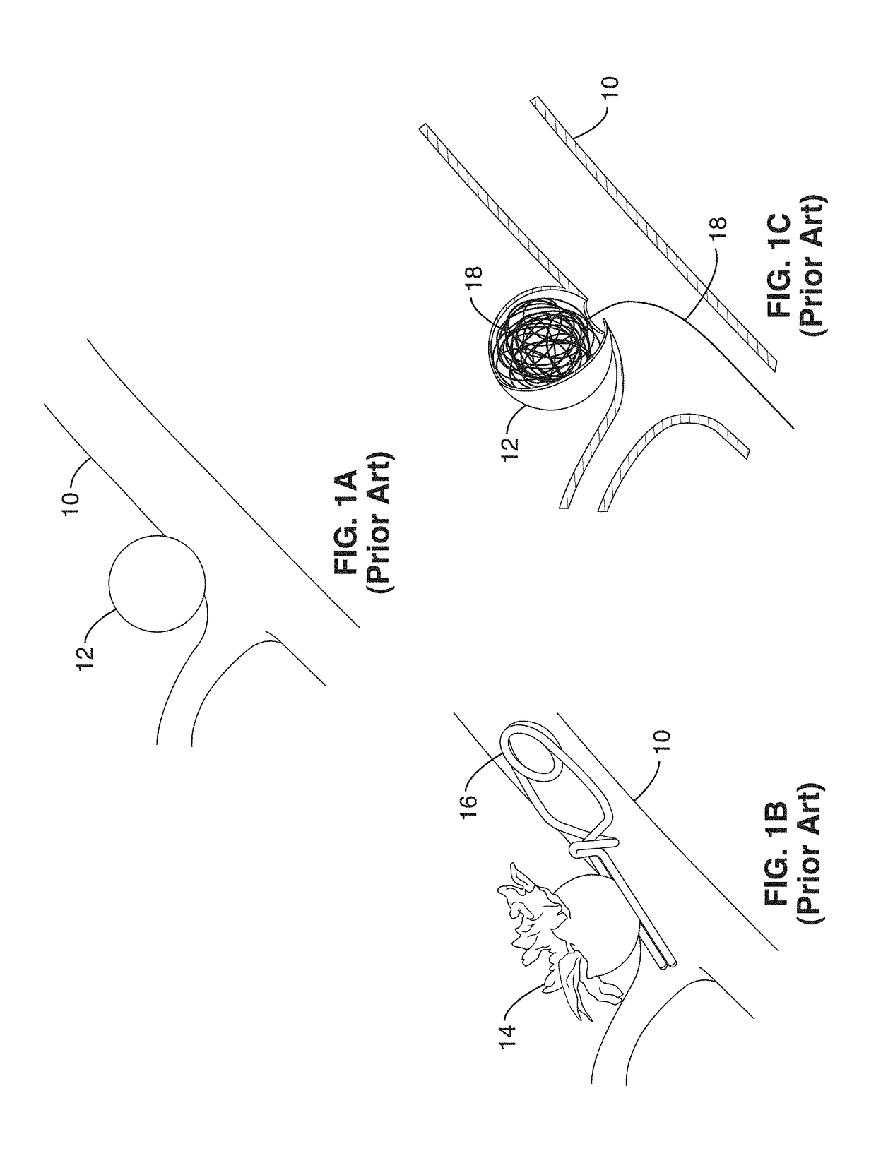
Aneurysms can occasionally rupture and cause a life threatening hemorrhage.
Aneurysm rupture carries a high rate of morbidity and mortality.
However, this procedure requires a craniotomy (an opening in the skull) and is not always applicable depending on the aneurysm size, location and complexity.
While coils are beneficial, they can only be used for aneurysms with “necks” narrow enough to hold coils in the aneurysm.
However, certain aneurysms are difficult to treat with the current endovascular coiling or coil embolization approach of FIG. 1C.
This procedure is complicated (it involves two types of devices—a stent and multiple coils) and is limited by the physical size of the stent's delivery system.
To date, the production of a highly flexible, durable, and thrombus-resistant stent material has not been achieved for all applications.
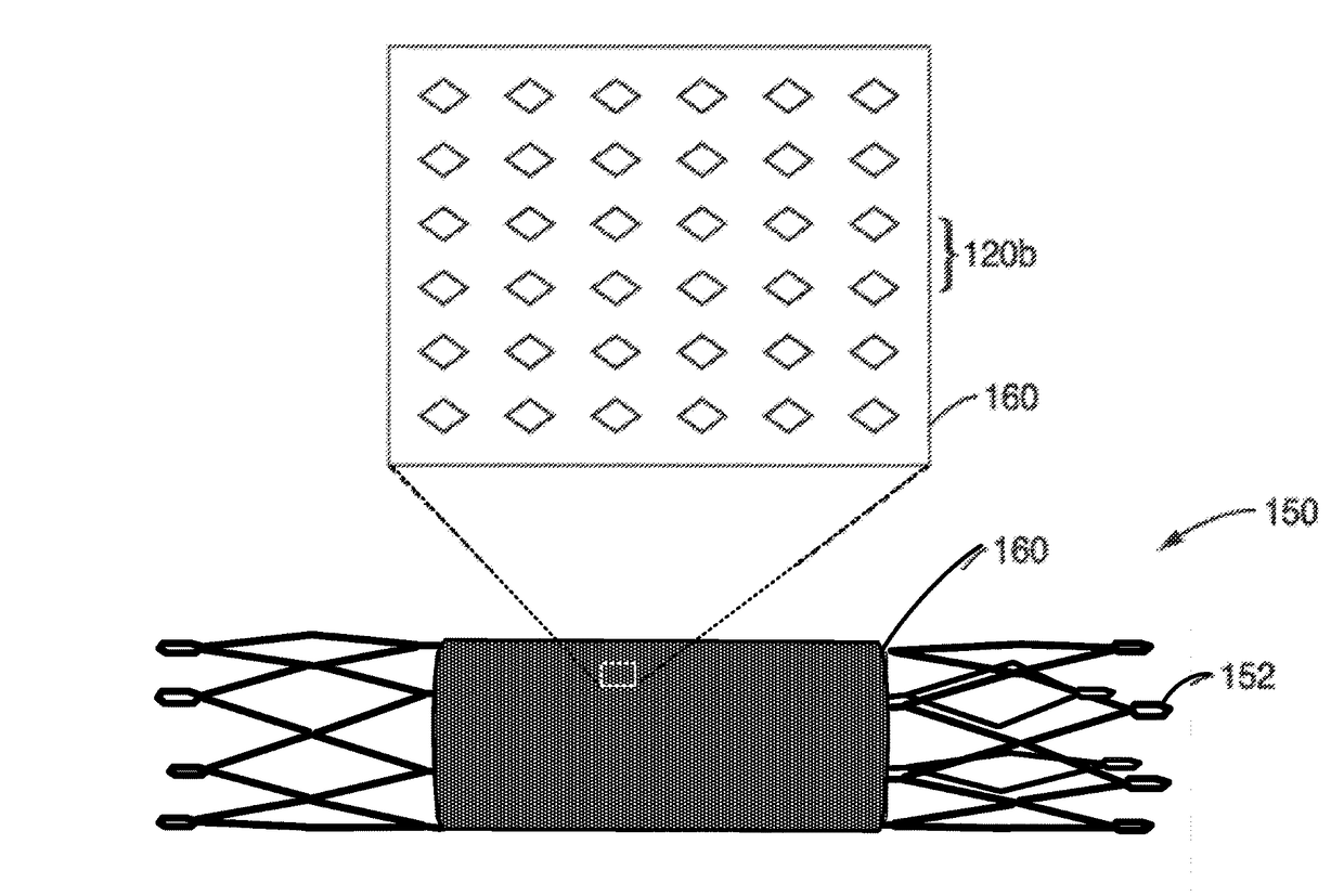
Covered stents generally have a thick covering, making the profile of the stent unacceptably large for certain applications, such as implantation in small and / or tortuous blood vessels, such as found in the vasculature supplying the central nervous system.
Accordingly, there are no commercially available covered stents that are low profile enough and flexible enough for use in the neurovasculature.
Thrombotic complications involving indwelling medical devices placed in the vascular are a challenge and burden to patients and our healthcare system as a whole.
The successful treatment of many diseases via endovascular techniques is particularly limited by clot formation on indwelling devices (such as stents).
However, these polymers bond poorly to grafts and have so far been relegated to laboratory science.
While there is evidence that hydrophilic surfaces reduce thrombogenecity, a successful approach that produces a super hydrophilic surface on metals currently used in vascular applications has been absent.
This method has been applied to thin film NiTi, but the results did not provide a superhydrophilic surface, and suggest that a superhydrohilic surface was not possible based on their methods.

Method used


Image

  • Thin film vascular stent and biocompatible surface treatment
  • Thin film vascular stent and biocompatible surface treatment
  • Thin film vascular stent and biocompatible surface treatment

Examples


embodiment 1

[0288]2. An implant , wherein the super-hydrophilic surface has a water contact angle of less than approximately 5 degrees.

[0289]3. An implant according to embodiment 1, wherein the super-hydrophilic surface is configured to deter platelet adhesion at a rate of less than 3 parts per mm2 when subjected to platelet rich plasma for 3 or more hours.

[0290]4. An implant according to embodiment 1, wherein the hydrophilic surface is fabricated by a method comprising the following: immersion of the thin film in a hydrogen peroxide solution.

embodiment 4

[0291]5. An implant , wherein the method further comprises: passivation of the thin film in a nitric acid solution prior to immersion of the thin film in a hydrogen peroxide solution.

embodiment 5

[0292]6. An implant , wherein the method further comprises: immersion of the thin film in a buffered oxide etchant to eliminate the native oxide layer prior to passivation of the thin film.


PUM

PropertyMeasurementUnit
water contact angleaaaaaaaaaa
thicknessaaaaaaaaaa
thicknessaaaaaaaaaa

Abstract

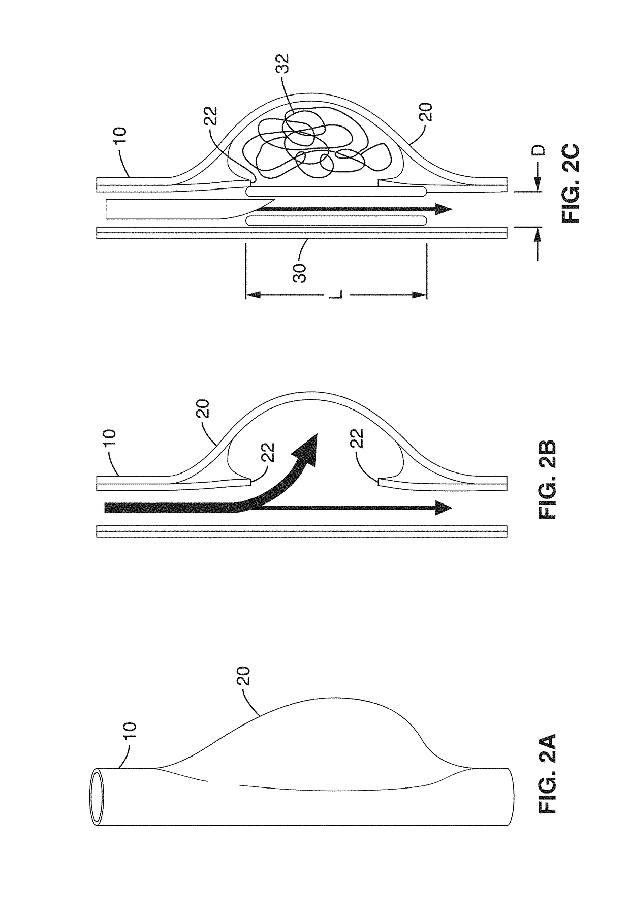
A vascular implant, comprising a sheet comprising thin film nickel titanium (NiTi), wherein the sheet has at least one super-hydrophilic surface having a water contact angle of less than approximately 5 degrees. The sheet is configured to have a compacted form having a first internal diameter and a deployed form having a second internal diameter larger than the first internal diameter. The sheet may be delivered into a blood vessel in the compacted form and expanded to its deployed form at a treatment location within the blood vessel, wherein the stent is configured to expand onto an internal surface of the blood vessel and exert a radial force on said internal surface.

Description

CROSS-REFERENCE TO RELATED APPLICATIONS[0001]This application a 35 U.S.C. §111(a) continuation of PCT international application number PCT / US2010 / 026430 filed on Mar. 5, 2010, incorporated herein by reference in its entirety, which is a nonprovisional of U.S. provisional patent application Ser. No. 61 / 158,200, filed on Mar. 6, 2009, incorporated herein by reference in its entirety, and from U.S. provisional patent application Ser. No. 61 / 158,221, filed on Mar. 6, 2009, incorporated herein by reference in its entirety. Priority is claimed to each of the foregoing applications.[0002]The above-referenced PCT international application was published as PCT International Publication No. WO 2010 / 102254 published on Sep. 10, 2010 and republished on Jan. 20, 2011, and is incorporated herein by reference in its entirety.STATEMENT REGARDING FEDERALLY SPONSORED RESEARCH OR DEVELOPMENT[0003]This invention was made with Government support under Grant No. W81XWH-07-1-0672 awarded by the U.S. Army,...

Claims


Application Information

Patent Timeline
Patent Type & Authority Patents(United States)
IPC IPC(8): A61F2/07A61F2/95A61L31/02A61B17/12A61F2/82A61F2/92A61F2/91
CPCA61F2/07A61B17/12022A61B17/12118A61F2/95A61L31/022A61L2400/18A61F2/91A61F2/92A61F2002/077A61F2002/823A61B2017/1205
Inventor LEVI, DANIEL S.CARMAN, GREGORY P.CHUN, YOUNGJAEVINUELA, FERNANDO
Owner RGT UNIV OF CALIFORNIA
Learn More