Evaporative heat transfer system

a heat transfer system and evaporative technology, applied in the field of heat transfer, can solve the problems of fundamental limitations in performance of such wicks, and inability to achieve significant increases in pumping power requirements, so as to achieve high capillary pressure and dissipate heat flux through the substrate

Active Publication Date: 2017-12-05
MASSACHUSETTS INST OF TECH
View PDF24 Cites 3 Cited by
  • Summary
  • Abstract
  • Description
  • Claims
  • Application Information

AI Technical Summary

Problems solved by technology

While heat transfer can be improved when in the annular flow regime with much higher exit quality, challenges exist with flow instabilities [3-5, 25-27].
Despite incorporating surface features and using various water mixtures allowing q″=600 W / cm2 and h=8.8 W / cm2K, the performance remains fundamentally limited by instabilities [28].
Accordingly, flow restrictors have been proposed [29], but lead to significant increases in pumping power requirements.
However, the performance of such wick is fundamentally limited due to the coupling between the capillary pressure generated by the wick and the liquid transport through the wick.
Even in this configuration, the liquid transport remains in the wick, and limits the maximum heat flux.
However, the configuration required heat conducting through a liquid layer that limited the thermal resistance, and active pumping, instead of capillarity, to drive the liquid to the membrane, which increased the power consumption.

Method used


Image

  • Evaporative heat transfer system
  • Evaporative heat transfer system
  • Evaporative heat transfer system

Examples


Embodiment Construction

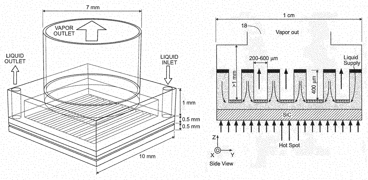
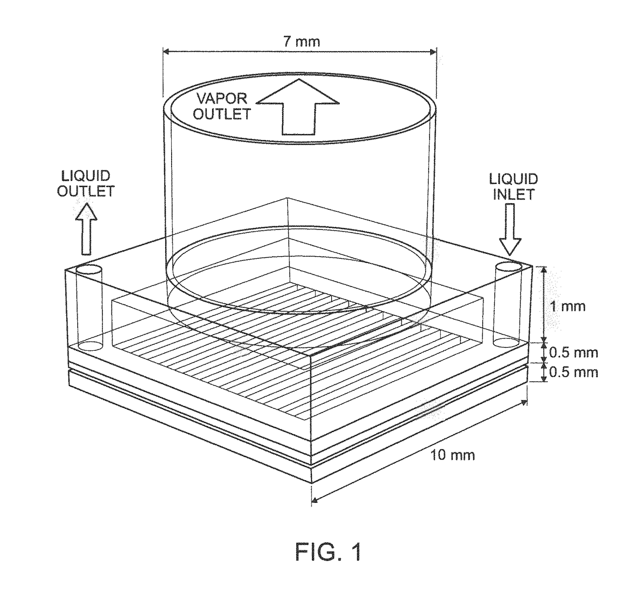
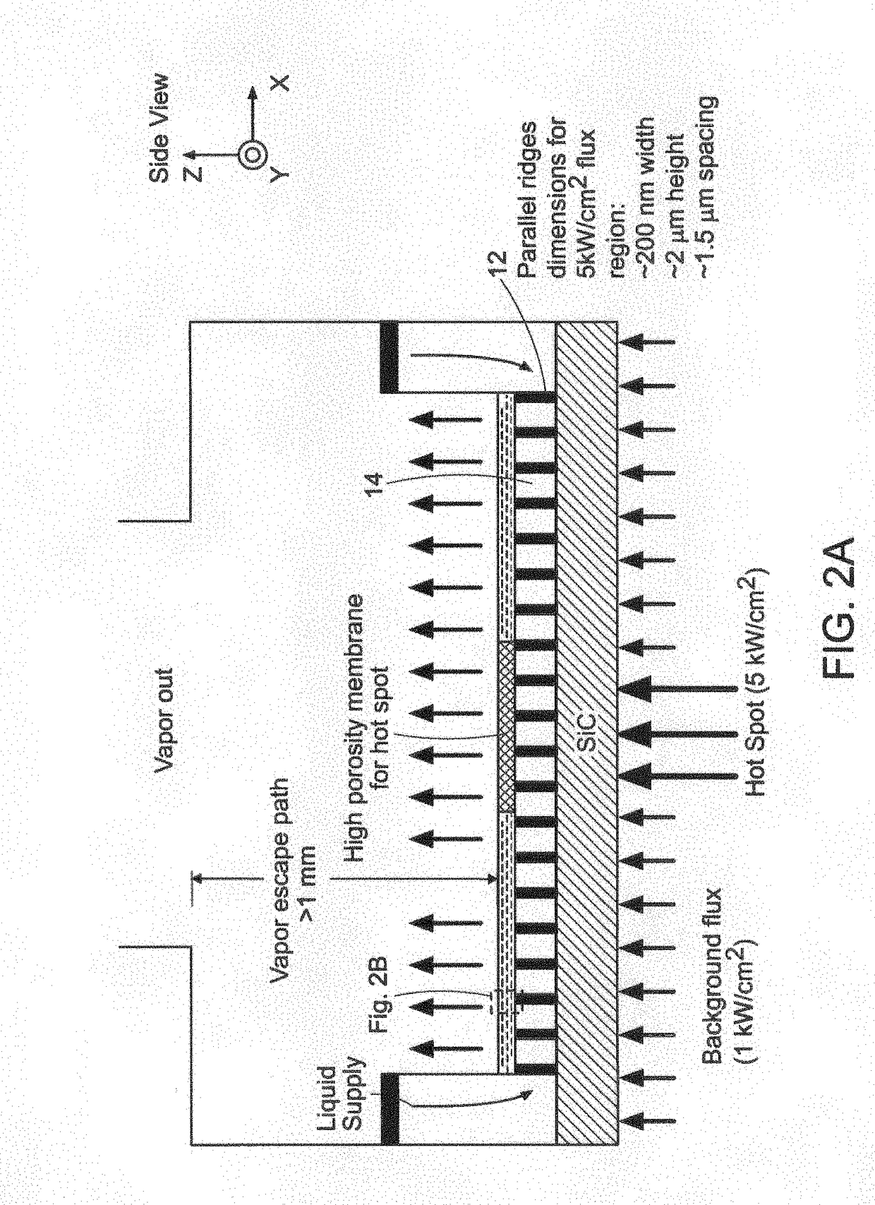
[0029]We disclose a unique intrachip two-phase evaporative cooling solution capable of dissipating >1 kW / cm2 for a 1 cm2 chip area with a local 200×200 μm2 hot spot >5 kW / cm2 (FIG. 1). A mechanical pump delivers a dielectric fluid, such as pentane, across microchannels whereby liquid is drawn in through the vertical liquid manifolds towards the heated surface via capillarity using a thin nanoporous membrane. The membrane provides an important functionality to the approach and allows the delivery of the necessary flow rates to dissipate the requisite heat fluxes. Subsequently, the vapor generated by evaporation exits through the backside and is guided to an external condenser where the liquid is recirculated back to the pump. A detailed design of the proposed concept is shown in FIG. 2, which has several important innovations.

[0030]A nanoporous membrane 10 is supported by parallel ridges 12 forming vertical channels 14 therebetween. Liquid is supplied through liquid supply lines 16. ...


PUM


Abstract

Evaporative heat transfer system. The system includes a substrate and a plurality of substantially parallel, spaced-apart ridges extending from the substrate forming vertical liquid manifolds therebetween. A nanoporous membrane is supported on the ridges and a pump delivers a dielectric fluid across the ridges. The fluid is drawn through the liquid manifolds via capillarity provided by the nanoporous membrane and evaporates to dissipate heat flux through the substrate. A preferred dielectric fluid is pentane. It is preferred that membrane porosity vary across the membrane to tailor thermal resistances to limit temperature rises.

Description

[0001]This non-provisional application claims priority to provisional application Ser. No. 61 / 752,013 filed on Jan. 14, 2013, the contents of which are incorporated herein by reference in their entirety.[0002]This invention was made with Government support under Grant No. N00014-09-1-1000 awarded by the Office of Naval Research. The Government has certain rights in the invention.BACKGROUND OF THE INVENTION[0003]This invention relates to heat transfer and more particularly to a heat transfer system using a nanoporous membrane to provide capillary pressure for high heat transport and decoupled from fluidic delivery.[0004]Increasing power densities in high performance systems have led to significant demands for advanced thermal management technologies. Evaporative microfluidic cooling strategies have received significant interest to address the stringent heat flux requirements in high performance systems while significantly reducing size, weight, and power consumption (SWaP). In partic...

Claims


Application Information

Patent Timeline
Patent Type & Authority Patents(United States)
IPC IPC(8): F25B39/02H01L23/427H01L23/473
CPCF25B39/02H01L23/427H01L23/473H01L2924/0002H01L2924/00
Inventor XIAO, RONGRAJ, RISHINARAYANAN, SHANKARWANG, EVELYN N.ENRIGHT, RYANMAROO, SHALABH CHANDRA
Owner MASSACHUSETTS INST OF TECH
Why Eureka
Try Eureka