Method and a system for generating a Raman second Stokes light to a source light

a technology of source light and raman, which is applied in the direction of basic electric elements, laser details, electrical apparatus, etc., can solve the problems of not being able to generate light using existing systems, less than desirable or practical performance of systems exploiting srs, etc., and achieve the effect of lowering the threshold for generation

Active Publication Date: 2017-12-05
MACQUARIE UNIV
View PDF2 Cites 3 Cited by
  • Summary
  • Abstract
  • Description
  • Claims
  • Application Information

AI Technical Summary

Benefits of technology

[0005]Disclosed herein is a method for generating a Raman second Stokes light to a source light. The method comprises the step of generating a Raman first Stokes light from the source light by a Raman interaction in a nonlinear optical medium disposed in an optical resonator, and resonating the Raman first Stokes light in the optical resonator. The method comprises the step of generating a seed light at the frequency of the Raman second Stokes light from the source light and the Raman first Stokes light by a four wave mixing process which is not phase matched in the nonlinear optical medium. The method comprises the step of amplifying the seed light by transferring power from the first Stokes light resonating in the optical resonator to the seed light using a Raman amplification process in the nonlinear medium. The method comprising the step of extracting from the optical resonator a majority of the power of the seed light so amplified. Resonating the first Stokes and using a four wave mixing process may greatly lower the threshold for generation of the Raman second Stokes light. Extracting the majority of the power of the seed light so amplified may relax the need for compensating the chromatic dispersion introduced by the nonlinear optical medium and optical resonator, which may be a substantial simplification.

Problems solved by technology

In some circumstances however, the performance of systems exploiting SRS may be less than desirable or practical, especially but not exclusively when the light comprises pulses of light of temporal width of around 1 n or less.
Some light may not be generated using existing systems exploiting SRS.

Method used


Image

  • Method and a system for generating a Raman second Stokes light to a source light
  • Method and a system for generating a Raman second Stokes light to a source light
  • Method and a system for generating a Raman second Stokes light to a source light

Examples


Embodiment Construction

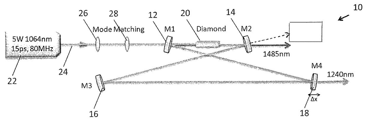
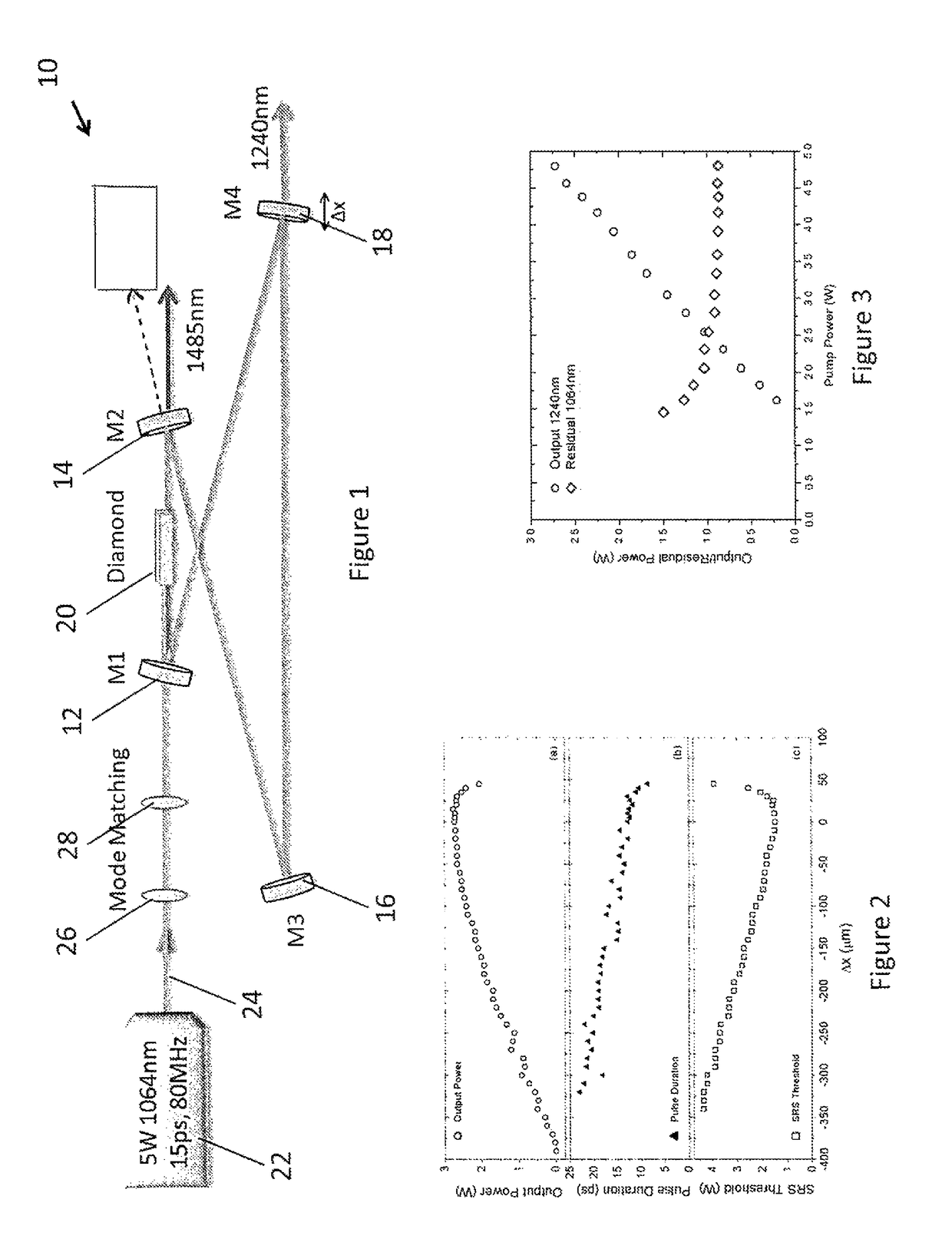
[0034]FIG. 1 shows a schematic diagram of an embodiment of a system for generating a Raman second Stokes light to a source light 24, the system being generally indicated by the numeral 10. The system 10 has an optical resonator that is in this embodiment an optical ring resonator in the form of a bow tie shaped optical ring resonator comprising in this embodiment two curved mirrors 12, 14 (labelled M1 and M2, and having a radius of curvature ROC=200 mm) and two flat mirrors 16, 18 (M3 and M4). The specification for each of the dielectric coated mirrors is summarized in Table 1. Light is extracted from the resonator by at least one mirror (“output coupler”), which is at least partially transmissive. Light may be extracted using generally any suitable light extractor. Disposed in the resonator is a nonlinear optical medium 20 that can support both Raman and four wave mixing interactions.

[0035]

TABLE 1Summary of mirror coatings.Mirror1064 nm1240 nm1480 nmM1, M3T = 93%R > 99.99%T = 90%M2...


PUM


Abstract

A method and system for generating a Raman second Stokes light to a source light comprising generating a Raman first Stokes light from the source light by a Raman interaction in a nonlinear optical medium disposed in an optical resonator, and resonating the Raman first Stokes light in the optical resonator; generating a seed light at the frequency of the Raman second Stokes light from the source light and the Raman first Stokes light by a four wave mixing process which is not phase matched in the nonlinear medium; amplifying the seed light by transferring power from the first Stokes light resonating in the optical resonator to the seed light using a Raman amplification process in the nonlinear medium; and extracting from the optical resonator a majority of the power of the seed light so amplified.

Description

CROSS REFERENCE TO RELATED APPLICATIONS[0001]This United States national phase application claims the benefit under 35 U.S.C. §371 of PCT Application No. PCT / AU2014 / 001078 filed on Nov. 27, 2014, which in turn claims priority to Australian Serial No. 2013904611 filed on Nov. 28, 2013 and all of whose entire disclosures are incorporated by reference hereinFIELD OF INVENTION[0002]The disclosure herein generally relates to a method and a system for generating a Raman second stokes light to a source light.BACKGROUND OF INVENTION[0003]Stimulated Raman scattering (SRS) has been used to generate light at frequencies for which it is difficult, inconvenient or impractical to generate using common and / or practical lasers.[0004]In some circumstances however, the performance of systems exploiting SRS may be less than desirable or practical, especially but not exclusively when the light comprises pulses of light of temporal width of around 1 n or less. Some light may not be generated using exist...

Claims


Application Information

Patent Timeline
Patent Type & Authority Patents(United States)
IPC IPC(8): H01S3/30H01S3/094H01S3/108H01S3/083H01S3/081
CPCH01S3/30H01S3/083H01S3/1086H01S3/094026H01S3/0816
Inventor SPENCE, DAVID JAMESCOUTTS, DAVIDMILDREN, RICHARD PAULPASK, HELEN MARGARETLIN, JIPENGWARRIER, ARAVINDAN
Owner MACQUARIE UNIV
Why Eureka
Try Eureka