Methods for radio frequency spectral analysis

Active Publication Date: 2017-12-19
MELAMED HOWARD +4
View PDF72 Cites 9 Cited by
  • Summary
  • Abstract
  • Description
  • Claims
  • Application Information

AI Technical Summary

Benefits of technology

[0015]Each of the plurality of filter modules correspond with a predetermined frequency band in the radio frequency spectrum or other user defined spectrum. Each filter module may comprise at least one filter for passing through desired signal frequencies or a frequency band, while filtering out other freque

Problems solved by technology

However, current methods employed in the measurement of interference sources and various signal characteristics presents a challenge.
Specifically, it would prove difficult to maneuver various radios or receivers for mapping a three dimensional view of signal characteristics with real obstacles.
Moreover, it may be burdensome or difficult to maneuver and/or to stabilize RF spectral analyzers in den

Method used


Image

  • Methods for radio frequency spectral analysis
  • Methods for radio frequency spectral analysis
  • Methods for radio frequency spectral analysis

Examples


Example

[0032]Like reference numerals refer to like parts throughout the several views of the drawings.

DETAILED DESCRIPTION OF THE PREFERRED EMBODIMENT

[0033]As shown in the accompanying drawings, the present invention is generally directed to a system and method for performing radio frequency (RF) spectral analysis.

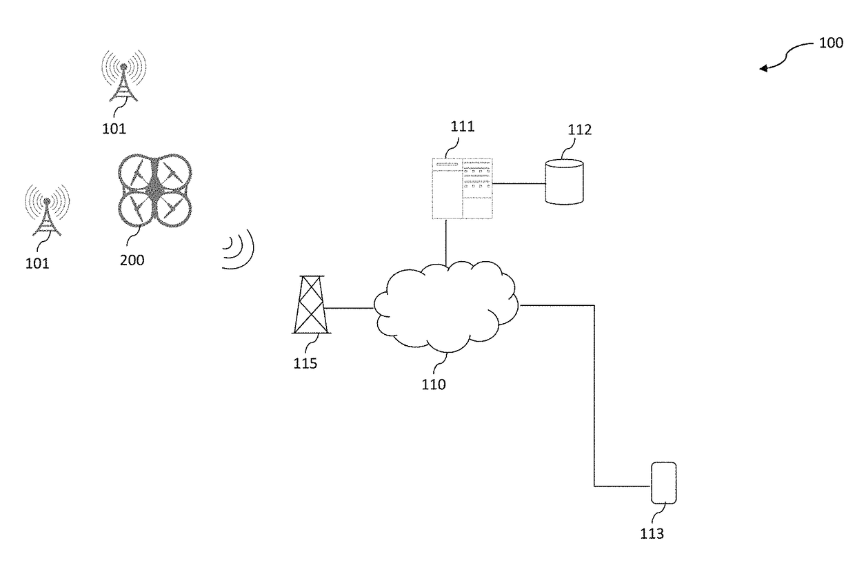
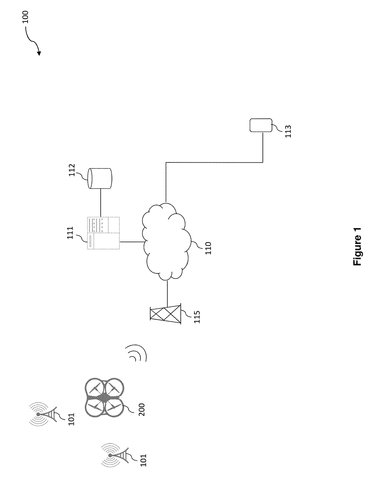
[0034]Accordingly, as shown in FIG. 1, a system 100 for RF spectral analysis generally comprises an unmanned aerial vehicle (UAV) 200 structured for flight and configured to detect radio signal(s) (at least one radio signal) produced by a signal source 101 and store various parameters of the radio signal(s) as signal data. In at least one embodiment of the present invention, the UAV 200 may store the signal data in onboard memory. In other embodiments, the UAV 200 may further be configured to transmit the signal data in real time or near real time to a receiver 115 communicably connected to a processing device 111 over a network. The processing device 111 may comprise an applicat...


PUM


Abstract

The invention is directed to methods for radio frequency spectral analysis. Accordingly, flight instructions are executed on a first UAV to fly in a first flight pattern relative to a signal source. The first UAV detects radio signal(s) from the signal source and associated signal data. Flight instructions are concurrently executed on a second UAV to fly in a second flight pattern, relative to the first flight pattern of the first UAV. The second UAV also detects radio signal(s) from the signal source and associated signal data. The stored signal data from the drones may then be processed for visualization.

Description

CLAIM OF PRIORITY[0001]This application claims the benefit of U.S. Provisional Patent Application No. 62 / 108,590, filed on Jan. 28, 2015. This application is also a continuation in part application of pending patent application Ser. No. 14 / 692,808 filed Apr. 22, 2015, which claims the benefit of U.S. Provisional Patent Application No. 62 / 045,220, filed Sep. 3, 2014, and U.S. Provisional Patent Application No. 62 / 045,209, filed Sep. 3, 2014, the contents of these applications are herein incorporated by reference.BACKGROUND OF THE INVENTIONField of the Invention[0002]This invention generally relates to systems and methods for performing radio frequency spectral analysis. Specifically, an unmanned aerial vehicle is utilized to measure radio signal(s) in real time, and to relay parameters thereof to a processing device over a network for analysis and visualization of the radio signal(s). A radio frequency pre-selector may be utilized to preselect a frequency band for performing the spec...

Claims


Application Information

Patent Timeline
IPC IPC(8): G08G5/00G08G5/02H04B17/391
CPCG08G5/0073G08G5/0008G08G5/025H04B17/391G08G5/0069B64C39/024G01R23/167G01R29/10B64U2201/104B64U2101/00G01R23/00
Inventor MELAMED, HOWARDMELAMED, STEVANSVANBERG, CHRISPONCE, MATIASHORVAT, MICHAEL
Owner MELAMED HOWARD
Why Eureka
Try Eureka