Electrical storage system for vehicle

a technology for electric storage and vehicles, applied in the direction of electric energy management, electric devices, safety/protection circuits, etc., can solve the problems of fuel economy deterioration, energy efficiency decline, and insufficient output of batteries for vehicles, so as to suppress the decrease in allowable output power, reduce the allowable output power, and eliminate degradation

Active Publication Date: 2017-12-26
TOYOTA JIDOSHA KK
View PDF21 Cites 16 Cited by
  • Summary
  • Abstract
  • Description
  • Claims
  • Application Information

AI Technical Summary

Benefits of technology

[0009]According to the above aspect, for example, even when the allowable output power is reduced in view of protection of the main battery, it is possible to compensate for the amount of electric power insufficient for the required vehicle output with an electric power from the auxiliary battery. Therefore, it is possible to keep supply of an electric power that satisfies a vehicle request. Even when the allowable input power is reduced in view of protection of the main battery, it is possible to charge part of regenerated electric power into the auxiliary battery when the regenerated electric power is not entirely charged into the main battery. Therefore, energy efficiency improves, and it is possible to suppress deterioration of fuel economy.
[0011]The controller may be configured to, when the evaluation value indicates a state where the ion concentration is biased toward a discharge side before the evaluation value exceeds the target value, discharge the auxiliary battery by using the bidirectional DC-DC converter and charge an electric power from the auxiliary battery into the main battery. By charging the main battery in a direction opposite to discharging in this way, it is possible to eliminate degradation resulting from a bias of the ion concentration due to discharging of the main battery. Therefore, it is possible to suppress a decrease in the allowable output power based on degradation resulting from a bias of the ion concentration.
[0012]In the above aspect, the controller may be configured to discharge the auxiliary battery by using the bidirectional DC-DC converter continuously after the evaluation value exceeds the target value, and charge an electric power from the auxiliary battery into the main battery. By reducing the allowable output power, it is possible to eliminate the state where the ion concentration is biased toward the discharge side while suppressing degradation resulting from the bias of the ion concentration. Therefore, it is possible to shorten a time during which an output limitation is imposed on the allowable output power.
[0013]In the above aspect, the controller may be configured to calculate a second evaluation value on the basis of the current value during charging and discharging of the main battery. The second evaluation value may be a value for evaluating a degradation component that reduces input performance of the main battery as a result of a bias of the ion concentration in the electrolyte due to charging of the main battery. The controller may be configured to reduce the allowable input power when the second evaluation value exceeds a second target value. The controller may be configured to, when the evaluation value indicates the state where the ion concentration is biased toward the discharge side, set a target SOC of an SOC of the auxiliary battery to a first SOC value higher than a predetermined SOC value. The controller may be configured to, when the second evaluation value indicates a state where the ion concentration is biased toward a charge side, set the target SOC of the SOC of the auxiliary battery to a second SOC value lower than the predetermined SOC value, and control charging and discharging of the auxiliary battery in accordance with the set target SOC. With this configuration, it is possible to ensure a large amount of electric power that is output from the auxiliary battery for a vehicle request at the time when the allowable output power is reduced. It is possible to ensure a large capacity for charging a regenerated electric power that is not entirely charged into the main battery at the time when the allowable input power is reduced.
[0014]In the above aspect, the controller may be configured to calculate a limited amount for reducing the allowable output power and a limited amount for reducing the allowable input power on the basis of each of first input / output limitations, second input / output limitations and third input / output limitations. The first input / output limitations, the second input / output limitations and the third input / output limitations are used for a non-aqueous secondary battery as the main battery. The first input / output limitations may be limitations for suppressing degradation that reduces input / output performance of the main battery as a result of a bias of an ion concentration in an electrolyte of the main battery due to charging and discharging of the main battery The second input / output limitations may be limitations for suppressing a temperature of a current-carrying component electrically connected to the main battery. The third input / output limitations may be limitations for suppressing an excess of an upper limit voltage or lower limit voltage of the main battery. The controller may be configured to supply an electric power to the power supply path by discharging the auxiliary battery and charge part of the regenerated electric power into the auxiliary battery on the basis of the calculated largest pair of limited amounts among the pairs of limited amounts. With this configuration, by reducing the allowable output power and the allowable input power on the basis of the most necessary pair of limited amounts from among the plurality of pairs of input / output limitations, it is possible to keep supply of an electric power that satisfies a vehicle request and suppress deterioration of fuel economy while appropriately protecting the main battery.

Problems solved by technology

However, in a state where the output (discharge) of the battery is limited, for example, the output of the battery becomes insufficient for a vehicle request.
In a state where the input (charge) of the battery is limited, for example, regenerated electric power is not entirely charged into the battery, so energy efficiency decreases and fuel economy deteriorates.

Method used


Image

  • Electrical storage system for vehicle
  • Electrical storage system for vehicle
  • Electrical storage system for vehicle

Examples


first embodiment

[0033]Hereinafter, embodiments of the invention will be described. A first embodiment will be described

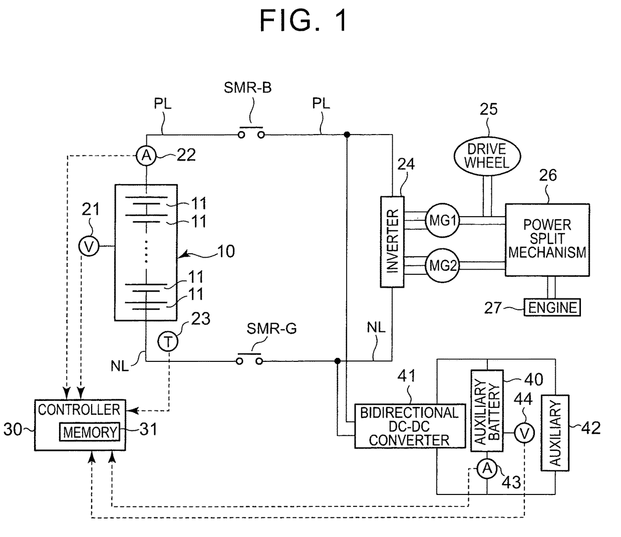
[0034]FIG. 1 is a view that shows the configuration of a battery system according to the present embodiment. The battery system according to the present embodiment may be mounted on a vehicle. The vehicle is a hybrid vehicle or an electric vehicle. The battery system shown in FIG. 1 is an example in which the battery system is mounted on the hybrid vehicle. The electric vehicle includes only a battery pack (described later) as a power source for propelling the vehicle.

[0035]A battery pack 10 is a main battery that supplies electric power for propelling the vehicle. The battery pack 10 includes a plurality of single cells 11 connected in series with each other. A secondary battery, such as a nickel-metal hydride battery and a lithium ion battery, may be used as each single cell 11. Instead of a secondary battery, an electric double layer capacitor may be used.

[0036]The number of the...

third embodiment

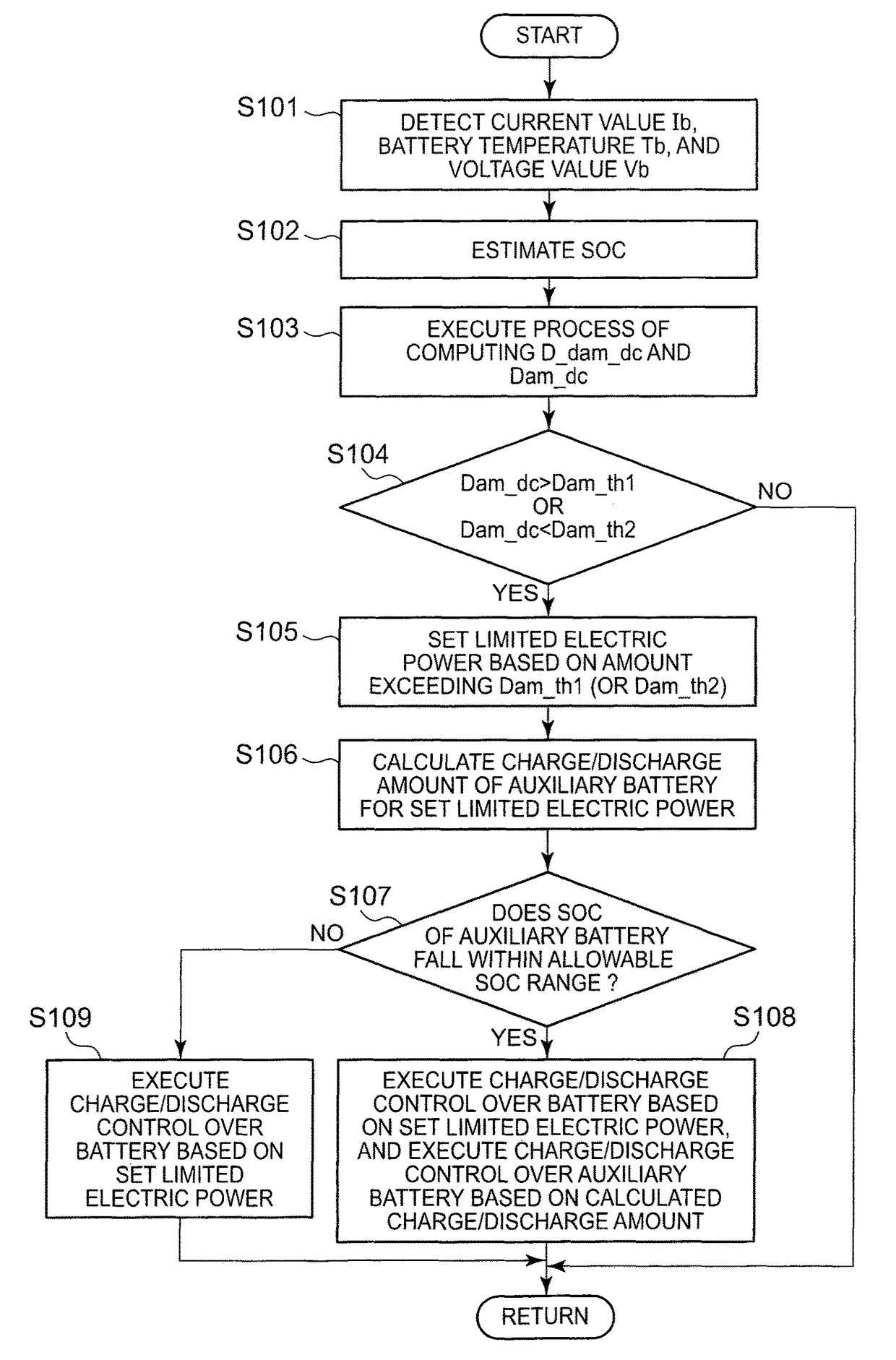
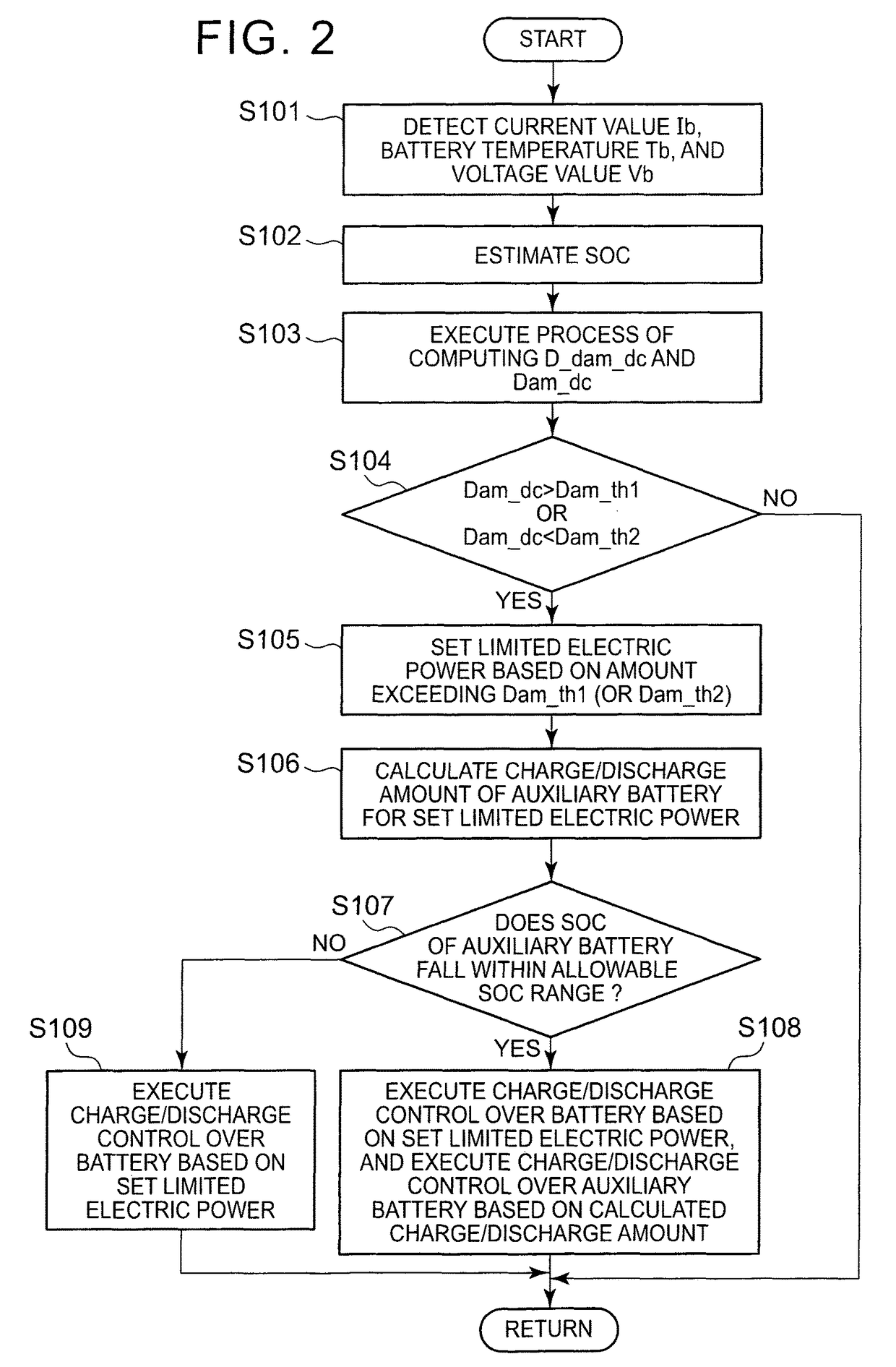
[0201]The battery pack 10 generates heat when charged or discharged, and the battery temperature Tb increases. It is known that battery degradation is accelerated when the battery temperature Tb increases to a high temperature, so it is required to appropriately control charge / discharge current. As in the case of the above-described third embodiment, charge / discharge currents of the battery pack 10 are also controlled in view of protection of current-carrying components. Therefore, an upper limit value of each of charge / discharge currents is set in advance, and, when charge current or discharge current that exceeds the upper limit current (overcurrent) flows through the battery pack 10, the controller 30 is able to execute charge / discharge control in which input electric power or output electric power is limited so as not to exceed the upper limit current.

[0202]Upper limit values of input and output powers (electric power excess thresholds) of the battery pack 10 may be obtained in ...


PUM

PropertyMeasurementUnit
electric poweraaaaaaaaaa
output voltageaaaaaaaaaa
poweraaaaaaaaaa

Abstract

An electrical storage system includes a main battery, an auxiliary battery, a bidirectional DC-DC converter and a controller. The bidirectional DC-DC converter is provided between the auxiliary battery and a power supply path from the main battery to a driving motor. The bidirectional DC-DC converter steps down an output voltage from the power supply path to the auxiliary battery, and steps up an output voltage from the auxiliary battery to the power supply path. The controller controls charging and discharging of the auxiliary battery. The controller, when an allowable output power of the main battery decreases and an electric power becomes insufficient for a required vehicle output, supplies an electric power to the power supply path by discharging the auxiliary battery by using the bidirectional DC-DC converter. The controller, when an allowable input power of the main battery decreases and a regenerated electric power generated by the driving motor is not entirely charged into the main battery, charges part of the regenerated electric power into the auxiliary battery by using the bidirectional DC-DC converter.

Description

BACKGROUND OF THE INVENTION[0001]1. Field of the Invention[0002]The invention relates to an electrical storage system that is mounted on a vehicle.[0003]2. Description of Related Art[0004]It is known that battery degradation is accelerated when the internal resistance of a secondary battery increases because of excessive charge and discharge. In Japanese Patent Application Publication No. 2010-060406 (JP 2010-060406 A), input and output powers of a secondary battery are limited on the basis of an estimated degree of increase in the internal resistance. Thus, battery degradation is suppressed.SUMMARY OF THE INVENTION[0005]However, in a state where the output (discharge) of the battery is limited, for example, the output of the battery becomes insufficient for a vehicle request. In a state where the input (charge) of the battery is limited, for example, regenerated electric power is not entirely charged into the battery, so energy efficiency decreases and fuel economy deteriorates.[00...

Claims


Application Information

Patent Timeline
Patent Type & Authority Patents(United States)
IPC IPC(8): B60L11/18B60L3/00B60L1/00B60L7/14B60L7/18H01M10/44H02J7/00H01M10/48H01M16/00G01R31/36H02J7/02
CPCB60L11/1811B60L3/0046B60L7/14B60L7/18B60L11/1857B60L11/1859B60L11/1861B60L11/1862B60L11/1868B60L11/1872H01M10/44H01M10/48H02J7/0029H02J7/0075H02J7/0091B60L1/00Y02T10/7233B60L2210/10B60L2210/12B60L2210/14B60L2240/545B60L2240/547B60L2240/549H01M10/486H01M16/00H01M2220/20H02J2007/004H02J2007/0037H02J2007/0039Y02T10/7005Y02T10/7044Y02T10/7066Y02T10/7225B60L53/20B60L58/16B60L58/14B60L58/13B60L58/20B60L58/25B60L58/15H02J7/0069H02J7/00302H02J7/00304H02J7/00306B60L58/26H02J2310/48Y02T10/70Y02T10/72Y02T10/92Y02T10/7072Y02T90/14Y02E60/10H02J7/007192H02J7/00309
Inventor TASHIRO, HIROKITANAKA, HIROMASANISHI, YUJITANABE, YUKINARIKAIYA, HIROYUKI
Owner TOYOTA JIDOSHA KK
Why Eureka
Try Eureka