
Cooling member and motor vehicle lighting or signaling device comprising such a member

a technology of motor vehicles and cooling components, which is applied in the direction of point-like light sources, lighting and heating apparatuses, transportation and packaging, etc., can solve the problems of enlargement of the surface dimensions reducing the luminous flux generating heat detrimental to the performance of the optical module, so as to achieve the effect of optimizing the cooling of the optical modul

Inactive Publication Date: 2018-01-02
VALEO VISION SA
View PDF15 Cites 0 Cited by
  • Summary
  • Abstract
  • Description
  • Claims
  • Application Information

AI Technical Summary

Benefits of technology

The invention provides an improved cooling system for optical devices such as lighting and signaling devices. By using an extension in the form of a base and fins, the dimensions of the cooling member are distributed inside the space, making available a larger exchange surface without enlarging the size of the member in a single plane. The fins are configured in such a way as to permit the convection of the air between them, and the result is an enlarged heat exchange surface, which makes it possible to optimize the cooling of the optical module and to adapt it to a more powerful light source in case of need. The cooling system is cost-effective and mechanically reliable.

Problems solved by technology

In the course of their operation, however, LEDs produce heat which is detrimental to their performance, since the greater the rise in the temperature of an LED, the greater is the reduction in its luminous flux.
The heat that is released may even give rise to problems relating to the adequate supply of electrical power to the LEDs.
This has the disadvantage of resulting in the enlargement of the surface dimensions of the optical module, which must be avoided in order to facilitate its implantation in the interior of the housing.
In addition, such implantation is likely to be difficult in view of the restricted nature of the space available to accommodate the one or more optical modules, and / or in view of the constraints associated with the general arrangement of the lamp unit in respect of its immediate environment when it is mounted on the vehicle.
The volume of the lighting devices may sometimes be large, however, and it is important to restrict their dimensions.

Method used


Image

  • Cooling member and motor vehicle lighting or signaling device comprising such a member
  • Cooling member and motor vehicle lighting or signaling device comprising such a member
  • Cooling member and motor vehicle lighting or signaling device comprising such a member

Examples


Embodiment Construction

[0051]Identical references are used below to designate identical or similar elements.

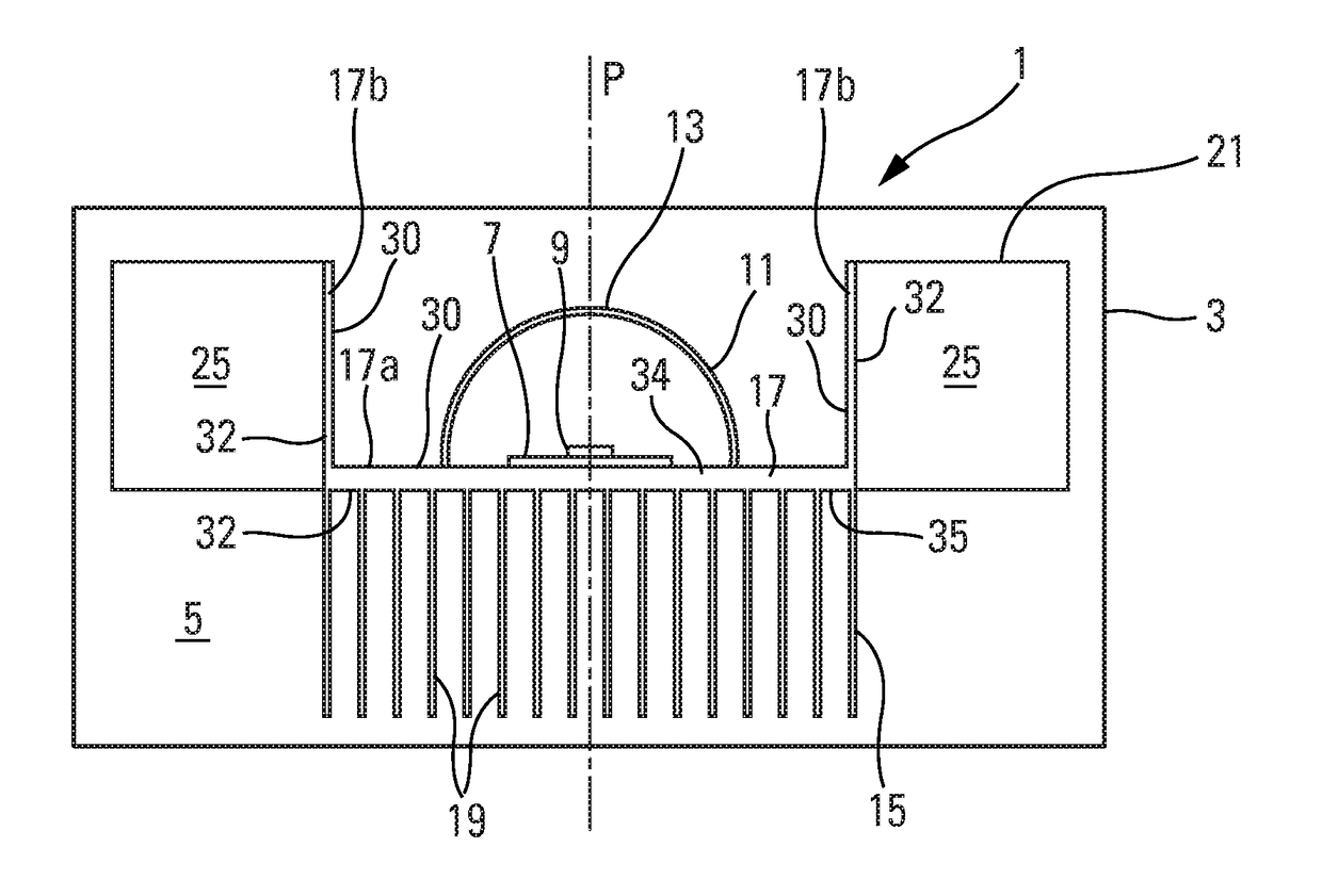
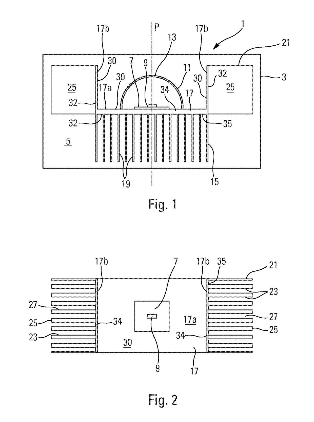
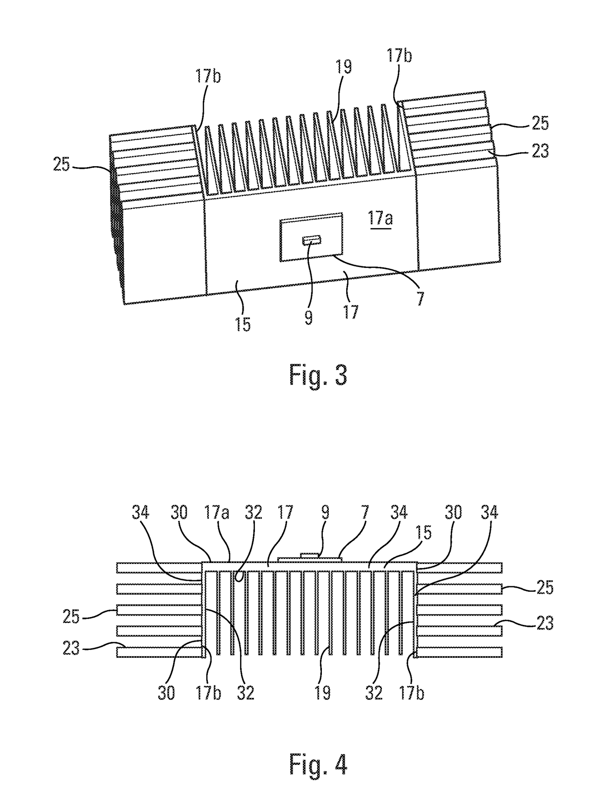
[0052]As illustrated in FIGS. 1 to 4, the invention relates to a lighting and / or signaling device 1 for a motor vehicle. It comprises a housing 3 closed by an outer transparent closing lens 5, as illustrated in a highly schematic manner.

[0053]The housing 3 in this case accommodates an optical module 7 for the emission of at least one global light beam via the outer transparent closing lens 5. This optical module 7 includes, for example, a light source 9 constituted by one or a plurality of LEDs. An optical system 11 is associated with the optical module 7. It is intended to modify at least one of the parameters of the light generated by the light source 9, such as its average reflection and / or its direction. In the example depicted, the optical system 11 comprises a reflector 13, which concentrates the light emitted by the light source 9 into a light beam in the direction of the outer transparent cl...


PUM


Abstract

A cooling member for a lighting and / or signaling device for a motor vehicle, the member comprising a base configured to support a light source of the device, and at least one heat dissipating device in thermal conduction connection with the base, the heat dissipating device comprising a plurality of heat dissipation fins, the base having large faces linked by a wafer, each of the fins extending from one of the large faces, the base extending in shape such that junction areas of at least two of the fins with the base extend in different planes.

Description

CROSS-REFERENCE TO RELATED APPLICATIONS[0001]This application is the U.S. National Phase application of PCT Application No. PCT / EP2014 / 058011 filed Apr. 18, 2014, which claims priority to the French application 1353628 filed on Apr. 19, 2013, which applications are incorporated herein by reference and made a part hereof.BACKGROUND OF THE INVENTION[0002]1. Field of the Invention[0003]The invention relates to a cooling member and a lighting or signaling device for a motor vehicle comprising such a member.[0004]2. Description of the Related Art[0005]Motor vehicle lighting or signaling devices are composed by and large of a housing that is closed by a transparent wall, through which one or a plurality of light beams emerge. This housing accommodates at least one optical module, largely comprising a light source, and an optical system capable of modifying at least one parameter of the light generated by the light source for the emission of the light beam by the optical module. The optica...

Claims


Application Information

Patent Timeline
Patent Type & Authority Patents(United States)
IPC IPC(8): F21V1/00F21V29/76F21V29/74
CPCF21S48/328F21S48/115F21S48/1154F21S48/215F21V29/767F21V29/74F21V29/76F21V29/763F21S48/321F21S41/143F21S43/14F21S45/48F21S45/49
Inventor HEINE, JEAN-BAPTISTEROUCOULES, CHRISTINE
Owner VALEO VISION SA
Learn More