Illumination device and projector

a technology of projector and projection device, which is applied in the direction of picture reproducers, picture reproducers using projection devices, instruments, etc., can solve the problems of high diffusing power of diffusion layer, difficulty in forming diffusion layer, and color unevenness, so as to achieve excellent display quality and reduce color unevenness

Active Publication Date: 2018-01-02
SEIKO EPSON CORP
View PDF9 Cites 1 Cited by
  • Summary
  • Abstract
  • Description
  • Claims
  • Application Information

AI Technical Summary

Benefits of technology

[0007]An advantage of some aspects of the invention is to implement an illumination device capable of expanding a light distribution of diffused light while reducing a reduction in light use efficiency. Another advantage of some aspects of the invention is to implement, by including the illumination device, a projector with, less probability of troubles such as color unevenness and having excellent display quality.
[0009]In the illumination device according to the aspect of the invention, an angular distribution of intensity of the beam bundle incident on the diffusion element shows a low value at the center and high values at the periphery. As a result, compared to the case where a beam bundle whose angular distribution of intensity has a high peak at the center is incident, the angular distribution of intensity of the beam bundle emitted from the diffusion element can be expanded. Since the angular distribution can be expanded without enhancing diffusion characteristics of the diffusion element, backscattering is reduced, and thus a reduction in light use efficiency can be reduced.
[0019]In the projector according to the aspect of the invention, the illumination device according to the aspect of the invention is included. Therefore, when the illumination device is combined with another illumination device, a difference in light distribution between the illumination device according to the aspect of the invention and another illumination device is reduced, and thus color unevenness can be reduced. Due to this, it is possible to implement the projector having excellent display quality.

Problems solved by technology

As a result, color uneveness may occur due to the difference in light distribution.
However, the diffusion layer with a high diffusing power has drawbacks such as much backscattering and difficulty in forming a diffusion layer with excellent characteristics.
Therefore, the use of the diffusion layer with a high diffusing power gives rise to the problem that light use efficiency is reduced due to the drawbacks.

Method used


Image

  • Illumination device and projector
  • Illumination device and projector
  • Illumination device and projector

Examples


first embodiment

[0031]Hereinafter, a first embodiment of the invention will be described with reference to FIGS. 1 to 8B.

[0032]In the embodiment, a projector in which laser light sources as solid-state light sources are used for ail of an illumination device for red light, an illumination device for green light, and an illumination device for blue light will be described by way of example.

[0033]Even when all of a plurality of illumination devices include solid-state light sources, a light distribution is different between different colored lights, and color unevenness may occur due to the difference in light distribution. In such a case, the illumination device according to the invention is suitably used.

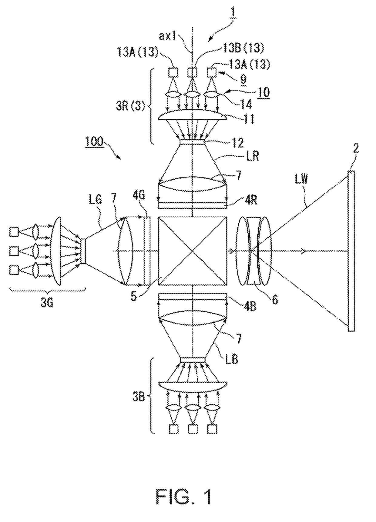
[0034]FIG. 1 is a schematic configuration diagram showing the projector according to the first embodiment.

[0035]In the drawings below, the components may be shown in different dimension scales for the sake of clarity of each component.

[0036]As shown in FIG. 1, the projector 1 is a projection-type i...

second embodiment

[0081]Hereinafter, a second embodiment of the invention will be described with reference to FIGS. 9 and 10.

[0082]In the embodiment, a projector including an illumination device that emits illumination light composed of fluorescence and diffused light will be described by way of example.

[0083]The fluorescence and the diffused light have basically different light distributions, so that color unevenness may occur due to the difference in light distribution. In such a case, the illumination device according to the invention is suitably used.

[0084]FIG. 9 is a schematic configuration diagram showing the projector according to the second embodiment.

[0085]FIGS. 9 and 10, components common to those m the drawings used in the first embodiment are denoted by the same reference and numeral signs, and a description thereof is omitted.

[0086]As shown in FIG. 9, the projector 21 includes an illumination device 22, a color separation optical system 23, the light modulator 4R for red light, the light...


PUM


Abstract

An illumination device includes a diffusion element and a light source device that emits a beam bundle including a first unit beam bundle to be incident on the diffusion element along a first direction and a second unit beam bundle to be incident on the diffusion element along a second direction. An angle formed by the first unit beam bundle with an optical axis of the beam bundle is greater than an angle formed by the second unit beam bundle with the optical axis, and the illumination device satisfies I2<I1 where I1 is a luminous flux of the first unit beam bundle, and I2 is a luminous flux of the second unit beam bundle.

Description

BACKGROUND[0001]1. Technical Field[0002]The present invention relates to an illumination a device and a projector.[0003]2. Related Art[0004]As one type of light source devices used for projectors, light source devices that irradiate a phosphor layer with laser light as excitation light to produce fluorescence at a wavelength different from the excitation light are proposed (e.g., see JP-A-2809-277516). A light source device disclosed in JP-A-2009-277516 has three fan-shaped segment areas on a circular transparent base. A red phosphor layer is provided in a first segment area, and red light is emitted from the first segment area. A green phosphor layer is provided in a second segment area, and green light is emitted from the second segment area. A diffusion layer is provided in a third segment area, and blue light as excitation light for the phosphor layers is emitted from the third segment area.[0005]In the light source device disclosed in JP-A-2009-277516, the red light, the green ...

Claims


Application Information

Patent Timeline
Patent Type & Authority Patents(United States)
IPC IPC(8): G03B21/20H04N9/31G02B5/02
CPCH04N9/3152G02B5/0278H04N9/3161H04N9/3164G03B21/208G02B5/02G02B5/0205
Inventor KASHIWAGI, AKIHIRO
Owner SEIKO EPSON CORP
Why Eureka
Try Eureka