Radiation imaging system and image processing device

a radiation imaging and image processing technology, applied in the field of radiation imaging systems and image processing devices, can solve the problems of difficult to accurately judge the change in signal(s), difficult to detect image quality deterioration, and physical quantities determined by imaging may contain errors

Active Publication Date: 2018-01-16
KONICA MINOLTA INC
View PDF3 Cites 7 Cited by
  • Summary
  • Abstract
  • Description
  • Claims
  • Application Information

AI Technical Summary

Benefits of technology

[0010]Further, according to a second aspect of the present invention, there is provided an image processing device which performs image processing on a plurality of periodic pattern images obtained by a radiation imaging device which includes at least one grating provided in an emission axis direction of radiation performing fringe scanning with a subject placed at a subject placement position provided on an emission path of the radiation while moving the grating, the image processing device including: a reconstruction unit which generates at least two reconstructed images of a differential phase image, an absorption image and a small-angle scattering image based on the periodic pattern images; and a detection unit which (i) performs regression analysis on signal values of at least two images of (a) the differential phase image, a differential absorption image generated by differentiating the absorption image, and a differential small-angle scattering image generated by differentiating the small-angle scattering image, or (b) a phase image generated by integrating the differential phase image, the absorption image, and the small-angle scattering image, (ii) calculates an indicator value of an indicator indicating a relationship between the at least two images, and (iii) detects image quality deterioration due to change in relative position of the radiation imaging device and the subject based on the calculated indicator value.

Problems solved by technology

However, if relative position (positional relationship) of the radiation imaging device and a subject changes while the radiation imaging device is taking M moire images by imaging of fringe scanning, physical quantities determined by the imaging may contain errors, and image quality deterioration may occur in a reconstructed image(s), which is generated by reconstruction of M moire images.
Further, although it is good if an operator can judge image quality deterioration due to change in relative position of the radiation imaging device and a subject from a reconstructed image(s) or moire images, it is difficult to accurately judge change in signal(s) due to movement of the radiation imaging device or the subject unless the radiation imaging device or the subject largely moves and strong artifacts appear.
For example, in medical use, if a target of interest is not captured in an image, its cause / reason cannot be identified; for example, the cause / reason may be no existence of the target from the beginning, image quality deterioration due to movement of the radiation imaging device or the patient, wrong positioning of the patient, or other error originated from the device or the like.
This leads to misdiagnosis or excessive exposure to radiation due to unnecessary re-imaging (re-fringe scanning) Similarly, in industrial use too, the above leads to a wrong examination result or excessive examination time.

Method used


Image

  • Radiation imaging system and image processing device
  • Radiation imaging system and image processing device
  • Radiation imaging system and image processing device

Examples


Embodiment Construction

[0046]In an embodiment below, the present invention is applied to a radiation imaging system using a Talbot-Lau interferometer. However, the present invention is not limited to one using a Talbot-Lau interferometer and hence is applicable to any radiation imaging system which uses at least a first grating, takes a plurality of periodic pattern images based on projection of the first grating or radiation intensity modulated by Talbot effect, and obtains at least two of a differential phase image, a small-angle scattering image and an adsorption image by calculation based on the principles of fringe scanning.

[0047]Hereinafter, an embodiment of the present invention is described with reference to the drawings.

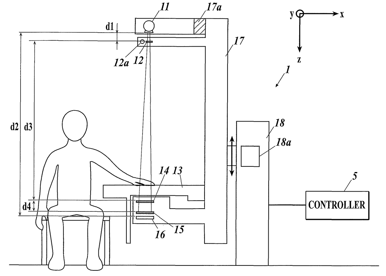
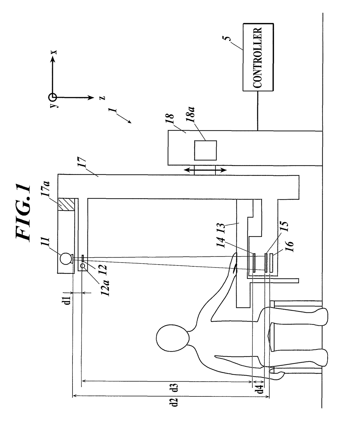
[0048]FIG. 1 shows a radiation imaging system according to an embodiment of the present invention. The radiation imaging system includes a radiation imaging device 1 and a controller 5. The radiation imaging device 1 performs X-ray imaging (fringe scanning) with a Talbot-Lau inter...


PUM


Abstract

A radiation imaging system includes a radiation imaging device, a reconstruction unit and a detection unit. The reconstruction unit generates at least two of a differential phase image, an absorption image and a small-angle scattering image based on periodic pattern images of a subject obtained by the imaging device. The detection unit performs regression analysis on at least two images of (a) the differential phase image, a differential absorption image of the absorption image and a differential small-angle scattering image of the small-angle scattering image or (b) a phase image of the differential phase image, the absorption image and the small-angle scattering image; calculates a value of an indicator indicating a relationship between the at least two images; and detects image quality deterioration due to change in relative position of the imaging device and the subject based on the value.

Description

CROSS-REFERENCE TO RELATED APPLICATIONS[0001]This U.S. application is based upon and claims a priority under the Paris Convention of Japanese Patent Application No. 2015-128503 filed on Jun. 26, 2015, the entire disclosure of which, including the specification, claims, drawings and abstract, is incorporated herein by reference in its entirety.FIELD OF THE INVENTION[0002]The present invention relates to a radiation imaging system and an image processing device.DESCRIPTION OF THE RELATED ART[0003]A radiation imaging device with a Talbot interferometer or Talbot-Lau interferometer employs a fringe scanning method to obtain high-resolution images. The fringe scanning method is a method of performing imaging M times (M is a positive integer of more than 2) while moving one of gratings 1 / M of a slit interval of the grating for each imaging in a slit interval direction, thereby obtaining images (moire images) for reconstruction.[0004]However, if relative position (positional relationship) ...

Claims


Application Information

Patent Timeline
Patent Type & Authority Patents(United States)
IPC IPC(8): G06K9/00G06T11/00A61B6/00G06T7/00
CPCG06T7/0002A61B6/4291A61B6/484A61B6/505A61B6/5211G06T11/005A61B6/5264G06T2207/30168A61B6/5205G06T2207/10116G06T2207/30008G16H50/20
Inventor MAKIFUCHI, CHIHO
Owner KONICA MINOLTA INC
Why Eureka
Try Eureka