Commutation cell

a commutation cell and cell technology, applied in the field of commutation cells, can solve the problems of high parasitic inductance of conventional commutation cells, and achieve the effect of preventing renewed melting and leaching and greater design freedom

Active Publication Date: 2018-01-16
ROBERT BOSCH GMBH
View PDF12 Cites 0 Cited by
  • Summary
  • Abstract
  • Description
  • Claims
  • Application Information

AI Technical Summary

Benefits of technology

[0005]In the commutation cell according to the present invention, the electrical components are not situated next to one another on a circuit substrate in the conventional manner. Moreover, no normally required wiring elements such as bonding wires, and usually required clearances, in particular for heat distribution, are provided between the electrical components. As a result, the present invention provides a commutation cell that is very compact in comparison to conventional commutation cells, thereby resulting in a minimization of the enclosed conductor loop and therefore, of the associated parasitic inductances. The commutation cell according to the present invention thus has three wiring planes which are situated on top of one another. The use of simple materials for the circuit substrates, such as copper, additionally results in cost advantages in comparison to conventional commutation cells. Moreover, the commutation cell according to the present invention has optimal heat dissipation characteristics since double-sided cooling and heat dissipation is possible in the vicinity of an electrical component that generates heat during its operation. Better heat dissipation characteristics may provide greater efficiency and, in particular, higher power densities, and thereby allow better utilization of materials.
[0015]According to one further advantageous development, the commutation cell has an external electrical insulation. The external electrical insulation may be realized by a casting or a second cast. Such a casting or second cast may also be used to create sufficient mechanical stability of a commutation cell and to satisfy requirements with regard to the moisture sensitivity threshold value (moisture sensitivity level / MSL), which is a measure for the loading capacity of the circuit by environmental effects. The exclusive provision of an external electrical insulation on a commutation cell allows maximum heat distribution in close proximity to the electrical components of the commutation cell. The electrical insulation may also include TIMs (thermal interface material). As an alternative, a circuit substrate may be developed as a ceramics-metal composite.

Problems solved by technology

Because of wiring elements such as bonding wires and required clearances between the electrical components, especially for heat distribution, conventional commutation cells have high parasitic inductances.
Moreover, in comparison with conventional complex manufacturing processes, this design results in cost advantages because of the relatively simple connection of two commutation cell parts so as to form a commutation cell.

Method used


Image

  • Commutation cell
  • Commutation cell
  • Commutation cell

Examples


Embodiment Construction

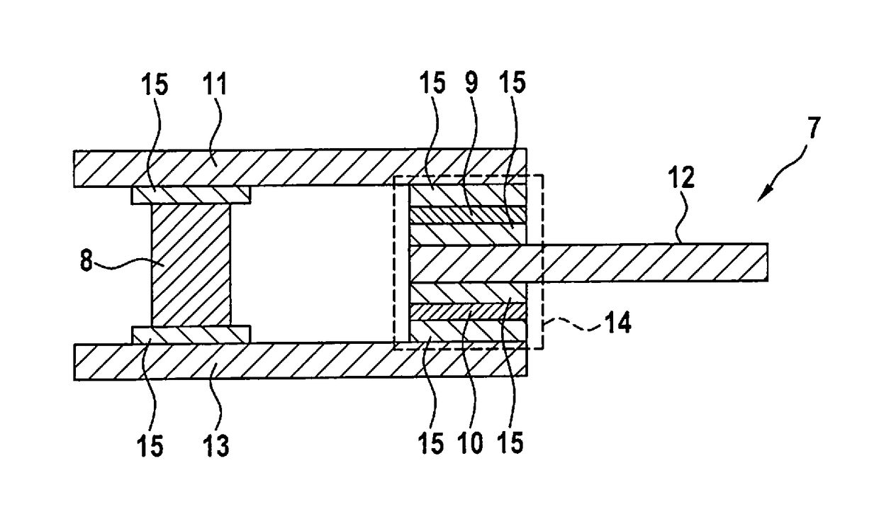
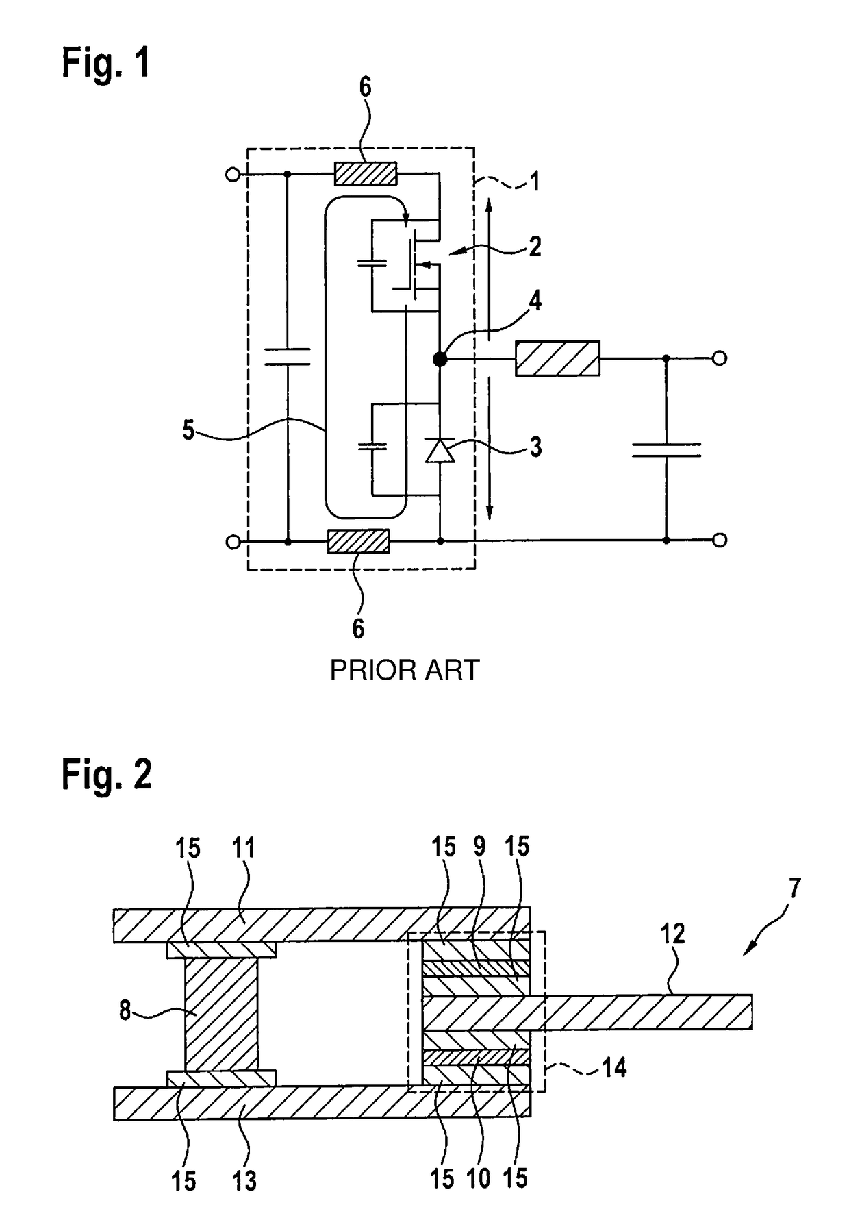
[0022]FIG. 2 shows a schematic representation of an exemplary embodiment for a commutation cell 7 according to the present invention. Commutation cell 7 has an electrical capacitor 8, a controllable semiconductor switch 9, and a semiconductor 10, which is connected in series with controllable semiconductor switch 9. In addition, commutation cell 7 has three circuit substrates 11, 12 and 13 situated in parallel with one another, the controllable semiconductor switch 9 being switched in series with semiconductor 10 via a circuit substrate 12 that is partially situated between controllable semiconductor switch 9 and semiconductor 10. The two remaining circuit substrates 11 and 13 are connected to each other in an electrically conductive manner via a subassembly 14 made up of controllable semiconductor switch 9, semiconductor 10 and circuit substrate 12 partially situated between controllable semiconductor switch 9 and semiconductor 10. Electrical capacitor 8 is switched between the two...


PUM


Abstract

A commutation cell having at least one electrical capacitor, at least one controllable semiconductor switch and at least one semiconductor which is connected in series with the controllable semiconductor switch. The commutation cell has three circuit substrates situated in parallel with one another. The controllable semiconductor switch is connected in series with the semiconductor via a circuit substrate situated partially between the controllable semiconductor switch and the semiconductor, and the two remaining circuit substrates being connected to one another in an electrically conductive manner via a subassembly made up of the controllable semiconductor switch, the semiconductor and the circuit substrate situated partially between the controllable semiconductor switch and the semiconductor, the electrical capacitor being switched between the two remaining circuit substrates, separately from the subassembly.

Description

BACKGROUND INFORMATION[0001]Commutation cells are parts of electrical circuits which, for instance, are installed in washing machines, fan-type ventilators, electrical power steering systems and electrical drives of motor vehicles.[0002]FIG. 1 shows an exemplary embodiment of a conventional commutation cell 1, in which a current modification initiated by a switching operation may come about. Commmutation cell 1 includes a controllable semiconductor switch 2 as well as a semiconductor diode 3, which is connected in series with the controllable semiconductor switch. An electric potential at a dynamic node 4 is modified with the aid of commutation cell 1. The physical realization of commutation cell 1 is defined by the geometry and other properties of the electrical components that are used for its development, and by circuit traces of commutation cell 1. Commutation cell 1 forms a conductor loop 5, which generates parasitic inductances in commutation cell 1 that are indicated schemati...

Claims


Application Information

Patent Timeline
Patent Type & Authority Patents(United States)
IPC IPC(8): H01L25/16H01L23/00H01L23/498H03K17/567
CPCH01L25/16H01L23/49833H01L23/49838H01L24/33H01L24/83H03K17/567H01L2224/29139H01L2924/0002H01L2224/32225H01L2224/33181H01L2224/8384H01L2924/00
Inventor DAVES, WALTERKASPER, KNUT ALEXANDERRITTNER, MARTINDUERNSTEINER, SILVIAGUENTHER, MICHAEL
Owner ROBERT BOSCH GMBH
Why Eureka
Try Eureka