Data processing apparatus and method for decoding program instructions in order to generate control signals for processing circuitry of the data processing apparatus

a data processing apparatus and program instruction technology, applied in the direction of program control, register arrangement, instruments, etc., can solve the problems of lack of flexibility in approach, limited ability of compilers to take advantage of actual physical registers, etc., and achieve simple and efficient encoding.

Active Publication Date: 2018-01-30
RGT UNIV OF MICHIGAN
View PDF9 Cites 0 Cited by
  • Summary
  • Abstract
  • Description
  • Claims
  • Application Information

AI Technical Summary

Benefits of technology

[0011]Such an approach has been found to provide a particularly efficient encoding, allowing a wide range of registers to be specified by a compact encoding within the instruction.
[0012]In accordance with the present invention, the compiler is able to have visibility of all of the registers within the register set, but each individual instruction is constrained to specify registers within one of the register groups. Since each register is a member of more than one register group, this still provides flexibility as to how the registers are used.
[0013]As a result of the use of the present invention, it is possible to specify more registers within a specified number of bits of the instruction encoding space than would otherwise be possible, or alternatively to use less bits of the instruction encoding space to specify a particular number of registers than would be required using conventional techniques.
[0014]The instruction decoder circuitry can be arranged in a variety of ways. However, in one embodiment, the instruction decoder circuitry comprises mapping circuitry configured to determine, in dependence on the group identifying data, mapping data indicative of the selected register group, and register access control signal generation circuitry configured to generate, for each selected member determined from the member identifying data, a corresponding register access control signal identifying the register corresponding to that selected member. For each selected member, the register access control signal generation circuitry is configured to apply the mapping data to the corresponding item of member identifying data in order to generate the corresponding register access control signal. Hence, in accordance with this embodiment, the group identifying data is used to produce mapping data which is then used in combination with each item of member identifying data in order to generate the corresponding register access control signal. This provides a very efficient mechanism for generating the required register access control signals identifying the registers to be accessed.
[0015]The group identifying data can take a variety of forms. However, in one embodiment, the group identifying data comprises M group bits and a group type indicator. Each item of member identifying data then comprises N bits. In addition, each register access control signal comprises M+N bits, and the mapping data generated by the mapping circuitry identifies the M group bits and the location that those M group bits are to occupy within the bit space of the register access control signal. Hence, in such embodiments, the mapping data directly uses the M group bits, and identifies at which bit positions within the bit space of the register access control signal those M group bits are to be used, with the remaining bits then being formed from the N bits of the corresponding item of member identifying data. This provides a very simple and efficient mechanism for generating the register access control signals from each item of member identifying data, dependent on the group identifying data.
[0016]Whilst the physical registers in the register set may be physically provided in any appropriate form, and hence in one embodiment may have a flat mapped structure, in one embodiment the set of registers are logically arranged as a multi-dimensional matrix of registers. In such an embodiment, each register group can be arranged to contain as members those registers located along an associated path within the multi-dimensional matrix. By using such a multi-dimensional matrix logical arrangement, this provides an efficient mechanism for defining the various register groups.

Problems solved by technology

However, such an approach is typically only used in high performance processors having multiple parallel execution paths, where the hardware overhead involved in performing register renaming is considered worthwhile for the performance benefits achieved.
In addition, register renaming limits the ability of the compiler to take advantage of the actual physical registers available.
Indeed, often the compiler must store operand values to memory because there are not enough architecturally visible registers for it to use within the program instructions.
However, such an approach lacks flexibility when seeking to perform operations on values from multiple contexts due to the different register windows associated with each context, and typically requires special instructions to change the context and accordingly change the mapping between the registers specified in the instruction and the actual physical registers accessed.

Method used


Image

  • Data processing apparatus and method for decoding program instructions in order to generate control signals for processing circuitry of the data processing apparatus
  • Data processing apparatus and method for decoding program instructions in order to generate control signals for processing circuitry of the data processing apparatus
  • Data processing apparatus and method for decoding program instructions in order to generate control signals for processing circuitry of the data processing apparatus

Examples


Embodiment Construction

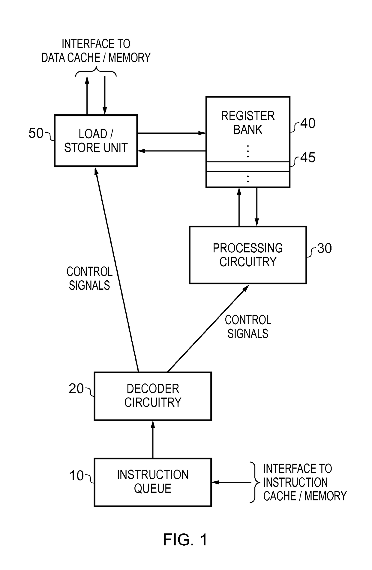
[0037]FIG. 1 is a block diagram of a data processing apparatus in accordance with one embodiment. In accordance with this embodiment, a stream of instructions are fetched from an instruction cache and / or memory, and placed in an instruction queue 10, from where the decoder circuitry 20 retrieves each instruction and decodes it in order to generate control signals sent to other components within the data processing apparatus. In particular, if the instruction is a load or store instruction used to load operand data from memory into the register bank 40, or to store operand data from the register bank back to memory, control signals will be sent to the load / store unit 50 in order to cause the required load or store operation to be performed. As will be understood by those skilled in the art, one or more levels of data cache may be provided between the load / store unit 50 and main memory, and accordingly data may be directly loaded in from one of the levels of the data cache into the re...


PUM


Abstract

A data processing apparatus and method for accessing operands stored within a set of registers. Instruction decoder circuitry, responsive to program instructions, generates register access control signals identifying for each program instruction which registers in the register set are to be accessed by the processing circuitry when performing the processing operation specified by that program instruction. The set of registers are logically arranged as a plurality of register groups, with each register in the set being a member of more than one register group. Each program instruction includes a register specifier field, and instruction decoder circuitry is responsive to each program instruction to determine a selected register group, and to determine one or more selected members of that selected register group. The instruction decoder circuitry then outputs register access control signals identifying the register corresponding to each selected member of the selected register group.

Description

BACKGROUND OF THE INVENTION[0001]Field of the Invention[0002]The present invention relates to a data processing apparatus and method for decoding program instructions in order to generate control signals for processing circuitry of the data processing apparatus.[0003]Description of the Prior Art[0004]Data processing circuitry will typically have access to a set of registers that are arranged to store operands for access by that data processing circuitry whilst it is performing data processing operations. The data processing operations that the data processing circuitry performs are typically defined by a series of instructions, where each instruction includes a register specifier field identifying the registers that are to form source and / or destination operands for the associated data processing operation.[0005]However, the instructions of a particular instruction set are typically constrained to a certain number of bits, and hence it is important to use the bit encoding space of t...

Claims


Application Information

Patent Timeline
Patent Type & Authority Patents(United States)
IPC IPC(8): G06F9/30G06F9/34G06F9/35G06F9/355G06F9/345
CPCG06F9/3012G06F9/3016G06F9/30098G06F9/3552G06F9/342G06F9/345G06F9/34G06F9/30156
Inventor PUSDESRIS, JOSEPH MMUDGE, TREVOR NMANVILLE, THOMAS D
Owner RGT UNIV OF MICHIGAN
Why Eureka
Try Eureka