Atrial appendage blood filtration systems

a technology of atrial appendage and filtration system, which is applied in the field of cardiac blood flow filtration, can solve the problems of atrial fibrillation, loss of circulation to the affected organ, blood pooling or stagnating in the patient's atrial appendage, etc., and achieves the effect of reducing the coupling stiffness of the tether wire, reducing the diameter, and sufficient rigidity

Inactive Publication Date: 2018-02-06
BOSTON SCI SCIMED INC
View PDF170 Cites 19 Cited by
  • Summary
  • Abstract
  • Description
  • Claims
  • Application Information

AI Technical Summary

Benefits of technology

[0008]The invention provides instrumentation for percutaneously implanting filter devices in atrial appendages to filter blood flowing between the atrial appendages and associated atrial chambers. The filter devices are designed to prevent dispersal of blood clots formed in the atrial appendages into the body's blood circulation system.
[0012]The distal portions of the access sheath are curved. The curvatures may be simple or compound. The curvatures take into account the anatomical geometry of the heart and are designed to provide a passageway leading directly to the subject atrial appendage. In an embodiment, the access sheath is made from J-shape tubing, with a distal portion that has a bend of about 90 degrees. In another embodiment, the access sheath is made from similar J-shape tubing, the distal portion of which has a further second bend away from the J-shape plane.
[0016]The delivery system may include remote actuators to expel or uncover filter devices for deployment. In one embodiment, a knob or handle is attached to the proximal end of the tether wire. The knob may be manipulated to translate or turn the tether wire. The tether wire is translated through the delivery tube to push the confined implant device out of the implant sheath. The tether wire diameter is selected to provide sufficient rigidity for transmitting mechanical translation and rotational forces to the attached implant device. Portions of the tether wire close to the attached implant device have a reduced diameter to reduce the coupling stiffness of the tether wire to the attached implant device. This reduced coupling stiffness is advantageous in deploying the device in its natural unbiased state while it is still attached to the tether wire.
[0017]In another embodiment of the delivery system, additionally or alternatively, the delivery tube is partially retractable over the tether wire into a handle portion. A sliding actuator, which is attached to the delivery tube, is disposed on the handle portion. The filter device may be expelled from the implant sheath by retracting delivery tube into the handle portion by activating the actuator on the handle portion. In either embodiment, distal portions of the tether wire adjoining the attached device may be encased in a flexible elastomeric material coil, which occupies the implant sheath lumen around the tether wire. The flexible coil reduces any buckling tendencies, which a moving flexible tether wire may have. Next, the tether wire may be detached by unscrewing it from the deployed device by turning a knob attached to the proximal end the tether wire. The delivery system may include mechanical features or releasable stops to limit the translation or rotation of the tether wire. Use of the releasable stops limits the possibilities for inadvertent expulsion of the device from the implant sheath and inadvertent release or loosening of the device attachment.
[0018]Both the access sheath and the delivery system tubes have suitable valve assemblies attached to their proximal ends to prevent fluid leakage during the device implantation procedure. The valve assemblies may include ports for injection of fluids through the various tube lumens. For example, the delivery catheter tube may be attached to a large bore Tuohy-Borst valve assembly. The Y-arm of the valve assembly may be used for intermittent or continuous fluid flushing and contrast injection or for continuous blood monitoring during the implantation procedure.

Problems solved by technology

Structural heart disease or other cardiac conditions in a patient can result in atrial fibrillation, which in turn causes blood to pool or stagnate in the patient's atrial appendage.
The blood clots may subsequently break off and migrate to the brain leading to stroke, or to other parts of the body causing loss of circulation to the affected organ.
However, not all patients cannot tolerate or handle the blood thinning drugs effectively.

Method used


Image

  • Atrial appendage blood filtration systems
  • Atrial appendage blood filtration systems
  • Atrial appendage blood filtration systems

Examples


Embodiment Construction

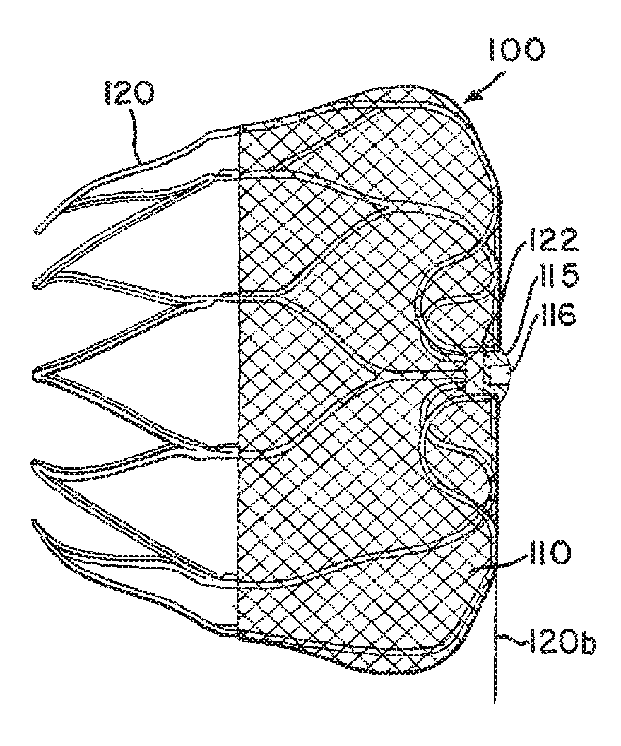
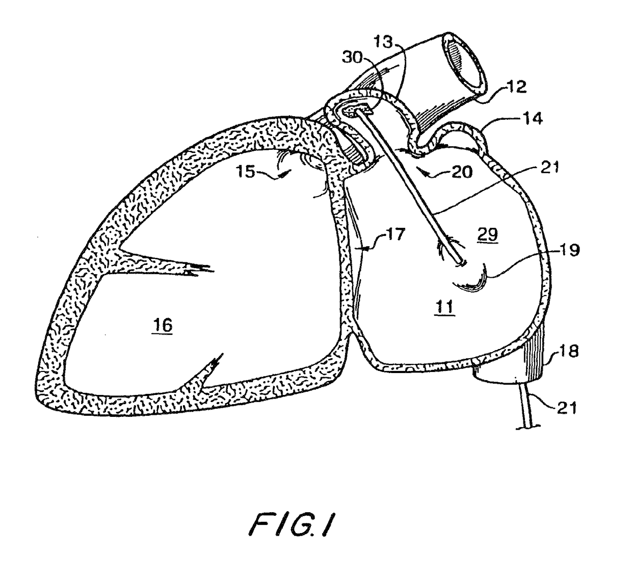
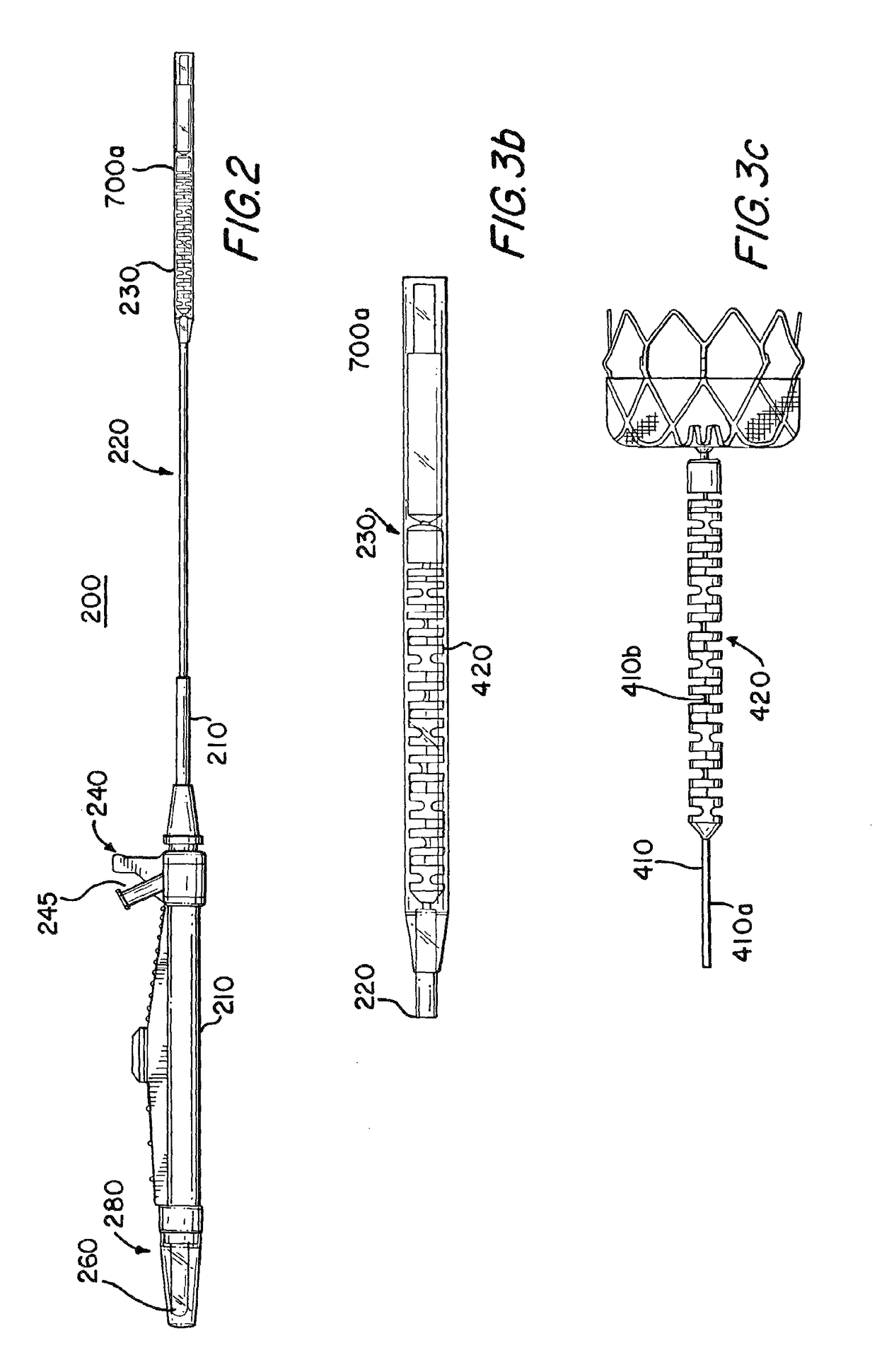
[0050]Devices for filtering or otherwise modifying blood flow between a left atrial appendage (LAA) and its associated atrium may be implanted in the LAA. A catheter access sheath is percutaneously coursed through a blood vessel leading to the heart to gain access to the LAA. A delivery system is used to move the device through the access sheath into the LAA. The delivery system includes a shaft or wire to control movement of the implant device.

[0051]Atrial fibrillation results in harmful clot formation primarily in the LAA. Therefore, it is anticipated that the invention will be mostly used for filtering blood flow from the LAA. However, it will be understood that the invention may also be used for the right atrial appendage and in general for device placement across any aperture in the body through which blood flows.

[0052]The implant filter devices may have adjustable sizes. A compact or narrow size is used for percutaneous device delivery to the atrial appendages, for example, by...


PUM


Abstract

Instrumentation for percutaneous delivery of blood filtration devices to atrial appendages includes a curved access sheath and a delivery tube. A compressed filter device attached to a tether wire is loaded in the delivery tube. The access sheath and the delivery tube can be mechanically locked and moved together to place the device in a suitable deployment position. The device is deployed by expelling it from the delivery tube either by retracting the delivery tube over the tether wire, or by moving the tether wire forward through the delivery tube. A filter membrane in the deployed device extends across the appendage ostium to filter blood flow through the ostium. The filter membrane is configured to present a flat surface to atrial blood flow past the ostium.

Description

[0001]This application is a continuation of U.S. application Ser. No. 10 / 351,736, filed Jan. 24, 2003, now abandoned, which claims the benefit of U.S. provisional application No. 60 / 351,898, filed Jan. 25, 2002, U.S. provisional application No. 60 / 379,921, filed May 10, 2002, U.S. provisional application No. 60 / 417,110, filed Oct. 8, 2002, and U.S. provisional application No. 60 / 403,720, filed Aug. 14, 2002, all of which are hereby incorporated by reference in their entireties herein.BACKGROUND OF THE INVENTION[0002]The invention relates to filtration of cardiac blood flow between an atrial appendage and its associated atrium. The blood filtration prevents the dispersal of thrombi, which may be formed in the atrial appendage, into the body's blood circulation system. In particular the invention relates to implant filter devices, and apparatus for the percutaneous delivery and implantation of such devices in the heart.[0003]Structural heart disease or other cardiac conditions in a pa...

Claims


Application Information

Patent Timeline
Patent Type & Authority Patents(United States)
IPC IPC(8): A61M29/00A61F2/01A61B17/00A61B17/12
CPCA61F2/01A61B17/12122A61B17/12172A61B17/0057A61F2230/0093A61B17/12022A61B2017/00243A61B2017/00575A61B2017/12095A61F2002/011A61F2002/016A61F2002/018A61F2230/005A61F2230/0006A61F2230/008A61F2/011A61F2/0105
Inventor SUTTON, GREGG S.WELCH, JEFFREYPETERSON, DEAN A.BRIDGEMAN, JOHN B.YOUNGBERG, BRUCE R.
Owner BOSTON SCI SCIMED INC
Why Eureka
Try Eureka