Method of fabricating a relay

a technology of relays and arcs, applied in the field of relays, can solve the problems of reducing the lifespan of the relay, reducing the service life of the relay, so as to prolong the length of the arc, increase the length, and accelerate the effect of removal

Active Publication Date: 2018-02-06
LSIS CO LTD
View PDF16 Cites 3 Cited by
  • Summary
  • Abstract
  • Description
  • Claims
  • Application Information

AI Technical Summary

Benefits of technology

[0011]Therefore, an aspect of the detailed description is to provide a relay capable of rapidly executing current interruption by having a permanent magnet which extends an arc, and a method of manufacturing the same.
[0021]Firstly, the relay is provided with the permanent magnet to induce an arc generated from the fixed contact and the movable contact, thereby extending a length of the arc. As the arc has an increased length, it may be rapidly removed. This may allow a current flow by the arc to be interrupted. Since a current may be rapidly supplied to a motor, components, etc. of an electric vehicle or the current supply may be rapidly interrupted, the motor or the components may be precisely controlled.
[0022]Secondly, since the permanent magnet is integrally formed with the housing, a size increase of the relay due to the permanent magnet may be prevented. This may maximize an arc extinguishing function of the relay without a size increase of the relay.

Problems solved by technology

However, in case of using the relay as a circuit switching device, the following problems may occur.
However, since the arc is a current flow and the fixed contact and the movable contact are connected to each other by the arc, current interruption is delayed by the arc even when the movable contact and the fixed contact are separated from each other.
Since current interruption is not rapidly executed, driving of the relay may not be precisely controlled.
This may cause the lifespan of the relay to be shortened.

Method used


Image

  • Method of fabricating a relay
  • Method of fabricating a relay
  • Method of fabricating a relay

Examples


Embodiment Construction

[0033]Description will now be given in detail of preferred configurations of a relay which is for an electric vehicle and which includes a permanent magnet, and a method of manufacturing the same according to the present invention, with reference to the accompanying drawings.

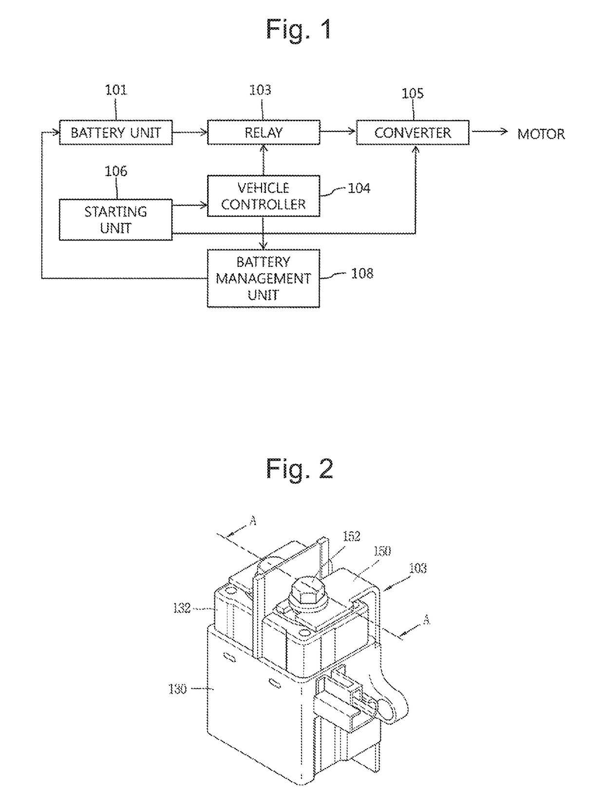
[0034]FIG. 1 is a block diagram illustrating a schematic structure of an electric vehicle according to the present invention.

[0035]As shown in FIG. 1, the electric vehicle according to the present invention includes a battery unit 101 configured to store electric energy of a high voltage; a relay 103 connected to the battery unit 101, and configured to supply a current output from the battery unit 101 to a motor or to interrupt current supply to the motor; a converter 105 connected to the battery unit 101 through the relay 103, and configured to convert a current supplied from the battery unit 101 as the relay 103 is operated and configured to output the converted current to the motor; a battery management unit ...


PUM

PropertyMeasurementUnit
temperatureaaaaaaaaaa
sizeaaaaaaaaaa
voltageaaaaaaaaaa

Abstract

The present invention relates to a relay for an electric vehicle and a method of manufacturing the same, and more particularly, a relay for an electric vehicle where a permanent magnet is integrally formed with a housing formed of a ceramic chamber, and a method of manufacturing the same. The relay, capable of rapidly executing current interruption includes: a fixed contact; a movable contact formed to contact or to be separated from the fixed contact; a shaft connected to the movable contact, and configured to move the movable contact; a housing configured to accommodate therein the fixed contact and the movable contact; an actuator configured to drive the shaft; and a permanent magnet integrally formed with the housing, and configured to extend an arc generated between the fixed contact and the movable contact. The permanent magnet includes an alnico-based material or a neodymium-based material.

Description

CROSS-REFERENCE TO RELATED APPLICATION[0001]Pursuant to 35 U.S.C. § 119(a), this application claims the benefit of earlier filing date and right of priority to Korean Application No. 10-2015-0101217, filed on Jul. 19, 2015, the contents of which are all hereby incorporated by reference herein in its entirety.BACKGROUND OF THE INVENTION[0002]1. Field of the Invention[0003]The present invention relates to a relay for an electric vehicle and a method of manufacturing the same, and more particularly, a relay which is for an electric vehicle and which has a permanent magnet integrally formed with a housing formed of a ceramic chamber, and a method of manufacturing the same.[0004]2. Background of the Invention[0005]Generally, an electric vehicle uses a motor using a battery power as a power source, and a hybrid electric vehicle uses a motor using an internal combustion engine and a battery power as a power source. In the electric vehicle or the hybrid electric vehicle, a plurality of batt...

Claims


Application Information

Patent Timeline
Patent Type & Authority Patents(United States)
IPC IPC(8): H01H11/00H01H49/00H01F1/03H01H9/44H01H51/06H01H65/00H01F41/02H01F7/02H01H50/02
CPCH01H51/065H01F1/0302H01F7/021H01H9/443H01H49/00H01H50/02H01F41/0266Y10T29/49105
Inventor LEE, KWANGSIK
Owner LSIS CO LTD
Why Eureka
Try Eureka