
Selectively bendable remote gripping tool

a remote access gripping and selective bend technology, applied in the field of selectively bendable remote access gripping tools, can solve the problems of affecting the quality of life of patients, and affecting the effect of patient comfort, so as to improve the quality of life, facilitate and facilitate use, and improve the effect of manipulating the function

Active Publication Date: 2018-02-27
KOVARIK CARTER J +1
View PDF212 Cites 11 Cited by
  • Summary
  • Abstract
  • Description
  • Claims
  • Application Information

AI Technical Summary

Benefits of technology

The invention is a surgical extractor that can capture and remove foreign or biological material from a patient's body. It uses a flexible corrugated member to reach and manipulate the material. The extractor has a jaw that can be adjusted to any angle, allowing the operator to peel off a bag from a patient's body and retrieve the contents. The extractor has spring-like fingers and a bag or netting material to capture the material. The technical effect of this invention is that it allows for safer and easier removal of foreign or biological material during surgical procedures.

Problems solved by technology

Such tools, however, are often complicated in terms of construction, often employing rails and jointed connections that rotate relative to each other to facilitate desired flexibility of the tool along at least an extent thereof.
However, these drugs can take several hours to be effective.
Moreover, peripheral venous embolisms may migrate to other areas of the body where even more serious untoward effects can result.
In cases where the thromboembolus is located within an artery, the normal flow of arterial blood may be blocked or disrupted, and tissue ischemia (lack of available oxygen and nutrients required by the tissue) may develop.
In such cases, if the thromboembolism is not relieved, the ischemic tissue may become infarcted (i.e., necrotic).
Depending on the type and location of the arterial thromboembolus, such tissue infarction can result in death and amputation of a limb, myocardial infarction, or stroke.
Notably, strokes caused by thromboembolic which become lodged in the small blood vessels of the brain continue to be a leading cause of death and disability, throughout the world.
However, the thrombolytic and / or anticoagulant drugs used in these pharmacologic treatments can cause untoward side effects such as bleeding or hemorrhage.
Also, in cases where time is of the essence, such as cases where an arterial thromboembolism is causing severe tissue ischemia (e.g., an evolving stroke or an evolving myocardial infarction) the time which may be required for the thrombolytic drugs to fully lyse or dissolve the blood clot and restore arterial blood flow may be too long to avoid or minimize the impending infarction.
Open surgical thrombus-removing procedures can, in many cases, be used to rapidly remove clots from the lumens of blood vessels, but such open surgical procedures are notoriously invasive, often require general anesthesia, and the use of such open surgical procedures is generally limited to blood vessels which are located in surgically accessible areas of the body.
For example, many patients suffer strokes due to the lodging of blood clots in small arteries located in surgically inaccessible areas of their brains and, thus, are not candidates for open surgical treatment.
However, such catheter-based interventional procedures are highly operator-skill-dependent, and can be difficult to perform in small or tortuous blood vessels.
Conventional baskets include Flatwire baskets, Helical baskets and Multi-wire baskets, each having their own disadvantages, such as flatwire baskets being unsuitable for capturing small calculi given the limited wires in such baskets providing too much space.
Accidental escapes of such baskets is common and damage to the adjacent tissue sometimes occurs during the treatment.
Known medical retrieval devices are complex in structure, requiring many components and labor-intensive manufacturing processes, and many do not provide controls for varying the size of the retrieval end of the device.

Method used


Image

  • Selectively bendable remote gripping tool
  • Selectively bendable remote gripping tool
  • Selectively bendable remote gripping tool

Examples


Embodiment Construction

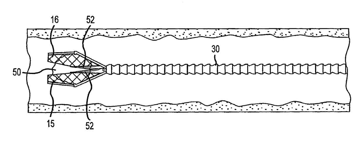
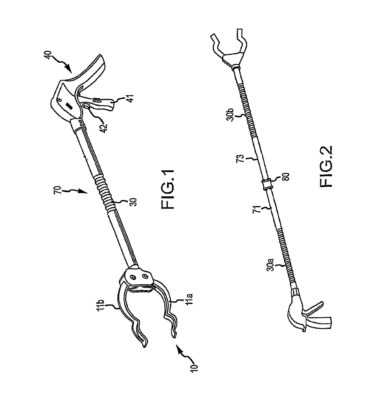
[0108]It will be understood that the disclosed embodiments are merely exemplary of the invention that may be embodied in various and alternative forms. The figures are not necessarily to scale, some features may be exaggerated or minimized to show details of particular components. Therefore, specific structural and functional details disclosed herein are not to be interpreted as limiting, but merely as a representative basis for teaching one skilled in the art to variously employ the present invention. For the following description, the actuatable tool head assembly is described as a gripper having a jaw assembly 11. It is understood, however, that any type of actuatable tool head assembly may be used.

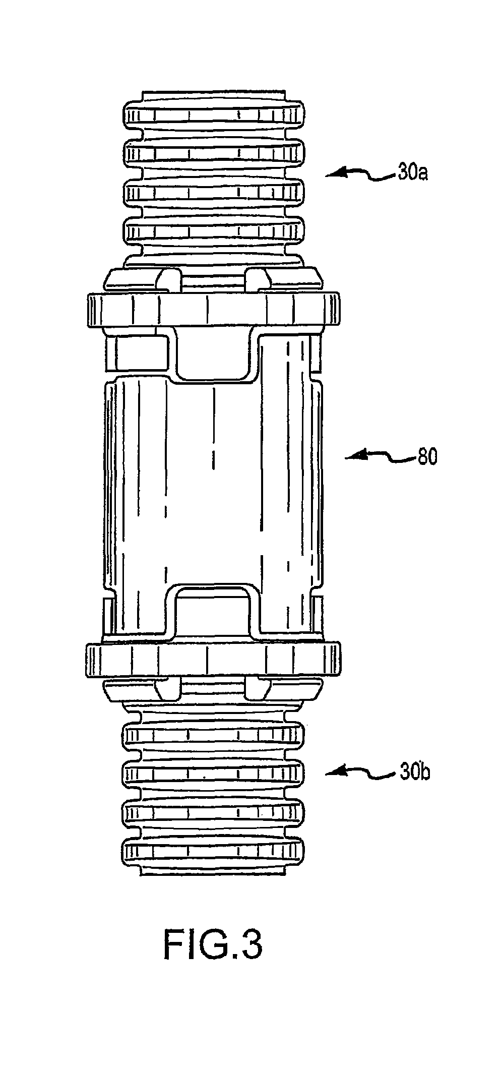
[0109]As disclosed in the figures, various embodiments of the present invention generally comprise a hand-held gripping device having a jaw portion (indicated generally at 10) comprising a pair of jaws 11a, 11b and a handle portion (indicated generally at 40) spaced apart by a selectiv...


PUM


Abstract

A hand-held gripping device that allows one of a surgeon, a dentist, and an orthodontist to reach interior portions of a person's anatomy, includes a gripping portion having a pair of jaws or nets movable relative to each other between fully clamped and fully opened positions thereof, a handle portion spaced apart from the jaw portion by a bendable central portion that has a hollow, bendable corrugated member with at least one cord extending therethrough. The retrieval of a thrombus to promptly address ischemic issues is made possible due to the flexible corrugated member being able to access small vessels in a patient's brain, as well as magnetic properties of the thrombus and / or jaws, nets, bags, or flexible fingers, of the grasping end, thus facilitating removal of the thrombus.

Description

RELATED APPLICATIONS[0001]This application is a continuation-in-part application of U.S. patent application Ser. No. 14 / 684,000, filed on Apr. 10, 2015, which is a continuation-in-part of Ser. No. 14 / 539,021, filed on Nov. 12, 2014, which is a continuation of U.S. patent application Ser. No. 14 / 535,539, filed on Nov. 7, 2014 (now U.S. Pat. No. 9,095,127, issued Aug. 4, 2015), which is a continuation-in-part of U.S. patent application Ser. No. 14 / 290,207, filed on May 29, 2014 (now U.S. Pat. No. 8,985,659, issued Mar. 24, 2015), which is a continuation-in-part of U.S. patent application Ser. No. 14 / 163,521 filed on Jan. 24, 2014 (now U.S. Pat. No. 8,833,817, issued Sep. 16, 2014), which is a continuation-in-part application of U.S. patent application Ser. No. 14 / 078,830 filed on Nov. 13, 2013 (now U.S. Pat. No. 8,807,615, issued Aug. 19, 2014), which is a continuation-in-part of U.S. patent application Ser. No. 13 / 771,813 filed on Feb. 20, 2013 (now U.S. Pat. No. 8,585,114, issued No...

Claims


Application Information

Patent Timeline
Patent Type & Authority Patents(United States)
IPC IPC(8): A61B17/22B25J1/02A61B17/221A61B1/05A61B1/00A61B1/06A01G3/025A61B17/00A61B17/29
CPCA61B1/0676A61B1/00087A61B1/05A61B17/221B25J1/02A61B17/22031A61B2017/2905A01G3/025A61B2017/00991A61B2017/2215
Inventor KOVARIK, CARTER J.KOVARIK, JOSEPH E.
Owner KOVARIK CARTER J
Learn More