Web-forming section and method for manufacturing multi-layer web

a technology of web and web layer, applied in the field of web-forming section, can solve the problems of generating fine washout from the vicinity of web surface, affecting the final use of the product, and affecting the quality of the finished product, so as to reduce the solid content of one or both fiber layers, increase production, and widen the couching stage running window

Inactive Publication Date: 2011-08-02
VALMET TECH INC
View PDF10 Cites 3 Cited by
  • Summary
  • Abstract
  • Description
  • Claims
  • Application Information

AI Technical Summary

Benefits of technology

Advantageously, a guide roll leading the travel of the second wire is placed in front of the couch shoe in the vicinity of the route of the first wire so that the second wire can be transferred from the guide roll to the couch shoe at a desired flat angle in relation to the first wire. The guide roll and the couch shoe are close to each other and fastened to the same support arm for facilitating wire change.
It is possible to design the openings of the deck of the shoe so that a pulsating effect is avoided. A dewatering pressure remaining substantially constant is achieved e.g. by means of openings which are individual holes or which are slots running askew over the cross-direction of the machine. By using non-pulsating dewatering in the joint area, it can be assured that the structure of the web is not damaged during the joining of fiber layers.
Alternatively, the surface of the deck can be designed so that pulsating dewatering is achieved. The pulsating dewatering is achieved e.g. by slots or grooves extending in the cross-direction of the machine. The pulsating dewatering improves the formation of the web and causes movement of fines in the web. The pulsating effect of grooves or slots can be intensified by connecting them to a source of underpressure.
The deck can also include both slots and holes. On the inlet side of the deck, there can be a slot which removes air flowing along with the wire which air can cause spots to the web as a result of a pressure pulse. By combining a pattern of slots and holes in a suitable way, the movement of fines can be intensified in the web.
When using an arrangement according to the invention, the fiber layers can be joined together wetter than usual. By means of the new embodiment, it is thus possible to widen the running window of the couching stage so that the solids content of one or both fiber layers can be decreased. This enables increasing production while using existing dewatering equipment. Correspondingly, on new board or paper machines the wire section can be made shorter than before. From the change in the geometry of the joint area also follows that a pipe roll, which is less expensive than the drilled-type roll traditionally used as the couch roll, can be used as the guide roll preceding the couch shoe. Furthermore, the number of auxiliary devices usually required by the couch roll can be decreased.
When the fiber layers are joined together on the curved surface of a stationary couch shoe, a sharp pressure pulse related to the rotation of the couch roll is avoided. Simultaneously, underpressure caused by the rotation of the roll is eliminated on the exit side of the couch nip. The radius of curvature of the shoe can be larger than the radius of curvature of the roll and further the radius of curvature can be different in different parts of the shoe. When the fiber layers are joined wetter than before, they will adhere to each other more strongly and the couch nip will not orientate the web. The suction transfers fines along with water from the lower fiber layer to the joint area thus improving interlaminar strength. In addition, it has been noticed that the couch shoe evens up the irregularities occurring in the moisture content of fiber layers before joining them together. By means of the couch shoe provided with suction, the solids content of the web exiting the web-forming section can be increased. A part of the dewatering previously implemented in connection with forming separate fiber layers is transferred to the joining stage of the fiber layers and to the dewatering stage following it.

Problems solved by technology

Splitting or delamination is a problem which occurs especially with board machines running liquid-packaging grades and multi-layer grades.
The question is then of coming loose of the upper or lower surface of the middle layer of a finished product, which causes severe problems in the end use of the product.
When one or both fiber layers are manufactured by gap former technique, low fines content in the boundaries being joined together can cause problems.
Two-sided dewatering is known to generate fines washout from the vicinity of web surfaces.
This can, however, cause problems in process management and cleansing.
Disadvantages related to the use of a couch roll are a sharp pressure pulse created in the nip and shear forces that cause orientation in the web.
Furthermore, the rotation of the roll creates an underpressure pulse to the exit side of the nip which pulse can damage the web and, in the worst case, make the newly joined fiber layers separate from each other.
At a too high solids content, it is difficult to obtain adequate interlaminar strength.
A too low solids content can cause splashings and faults in the joined web.
Many times the extension of the wire section is not possible or cost-effective because of lack of space.
If both have already been done, increasing production is difficult.
At high running speeds, there is a risk that the fiber layer is detached from the wire in consequence of centrifugal force.
Then, a sharp pressure pulse is created in the joint area which can damage the web being formed.
The method and the apparatus used in it are, however, complex.
Furthermore, dewatering from a so-called middle layer being fed between the fiber layers is difficult, because it takes place through two already drained fiber layers.

Method used


Image

  • Web-forming section and method for manufacturing multi-layer web
  • Web-forming section and method for manufacturing multi-layer web
  • Web-forming section and method for manufacturing multi-layer web

Examples


Embodiment Construction

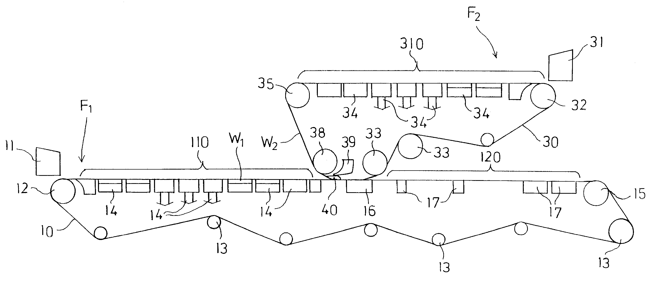
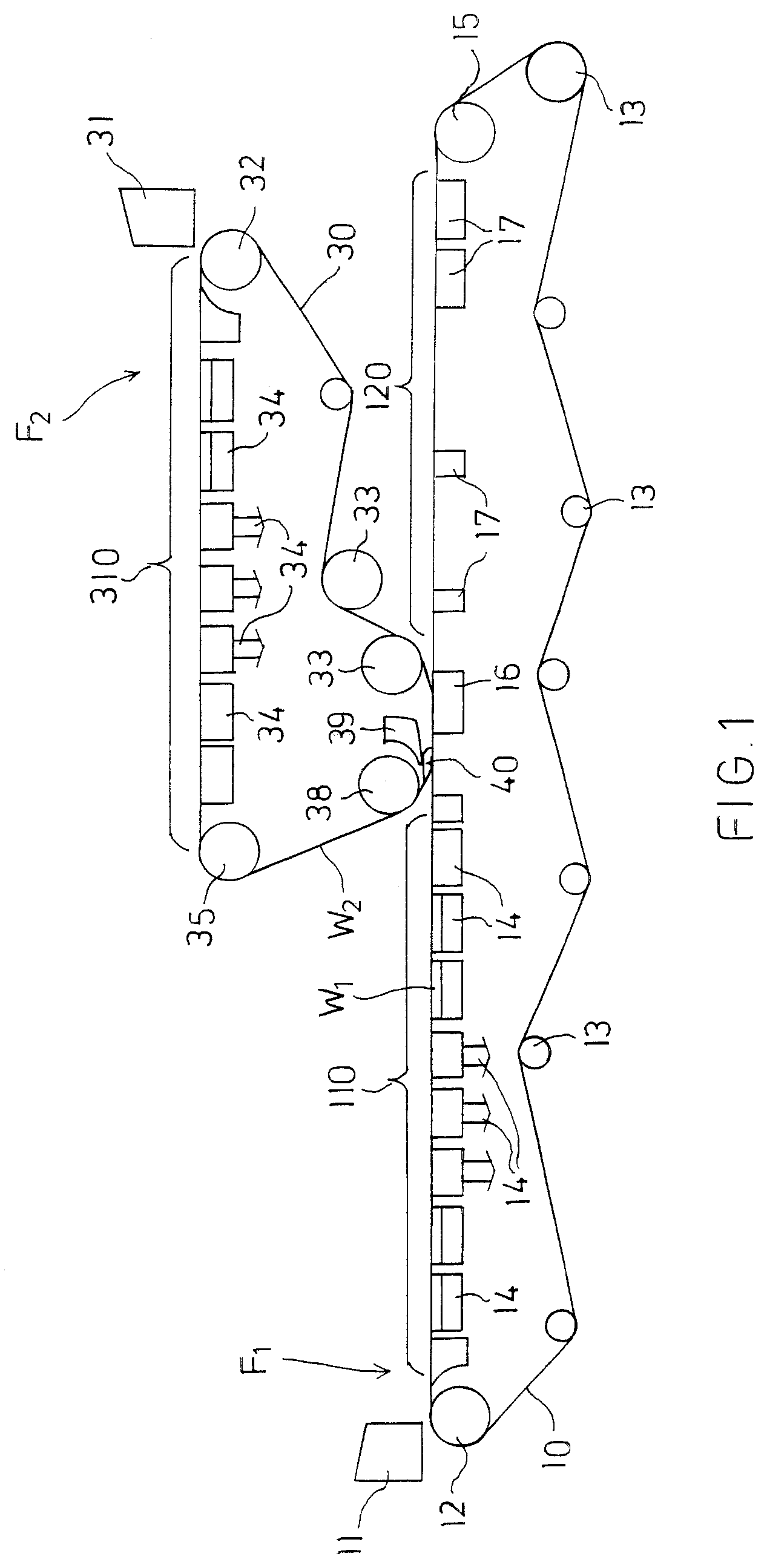
FIG. 1 schematically shows a web-forming section of a board machine producing a two-layer fiber web. It comprises a first web-forming unit F1 on which a first fiber layer W1 is formed, a second web-forming unit F2 on which a second fiber layer W2 is formed, and means for joining the separately formed fiber layers together.

The first web-forming unit F1 comprises a first headbox 11 and a lower wire 10 which runs substantially horizontally from a breast roll 12 to a turning roll 15 from which it returns back guided by guide rolls 13. Stock suspension is fed from the headbox 11 over the breast roll 12 to the lower wire 10, in a first Fourdrinier wire section 110 of which water is removed from the stock suspension by means of dewatering elements 14 located below the wire 10 for forming the first fiber layer W1. The dewatering elements 14 can be any dewatering elements commonly used on a Fourdrinier wire.

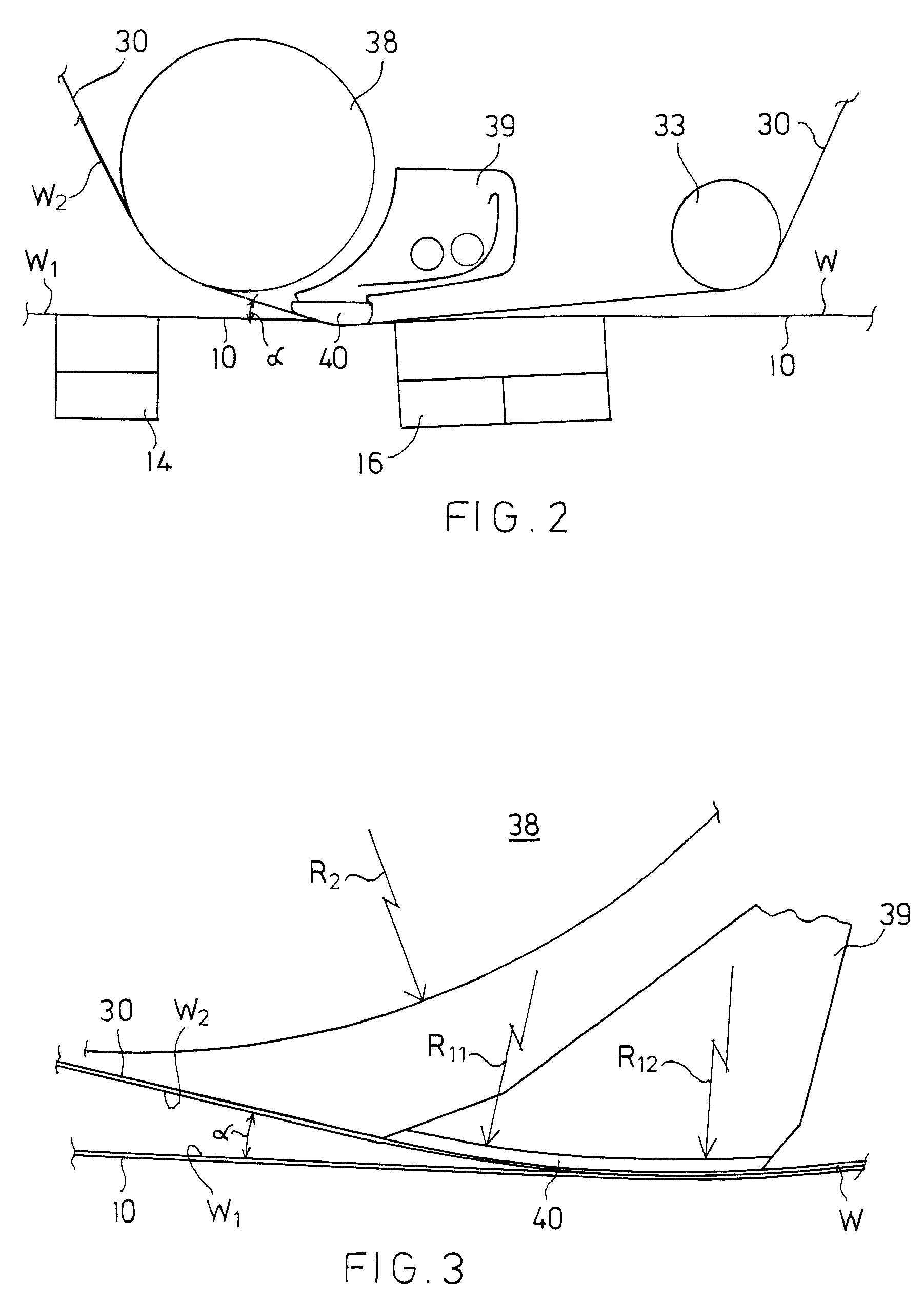
The horizontal portion of the lower wire 10 is divided into three parts which are the...


PUM

PropertyMeasurementUnit
angleaaaaaaaaaa
angleaaaaaaaaaa
incidence angleaaaaaaaaaa

Abstract

A web-forming section of a paper or board machine has a first web-forming unit with a first fiber layer (W1) formed on a first wire (10); a second web-forming unit with a second fiber layer (W2) formed on a second wire (30); and a couch shoe (39) over a curved deck (40) of which the fiber layers (W1, W2) are guided for joining them together. The second fiber layer (W2) is brought to the couch shoe (39) at an angle (α) of less than 20°, advantageously less than 15° in relation to the approach direction of the first fiber layer (W1). The couch shoe (39) is provided with underpressure and the radius of curvature of its deck (40) is usually larger than the radius of curvature of a guide roll (38) preceding it. By the couch shoe, the fiber layers can be joined together wetter than usual.

Description

CROSS REFERENCES TO RELATED APPLICATIONSThis application is a U.S. national stage application of International App. No. PCT / FI2006 / 050459, filed Oct. 25, 2006, the disclosure of which is incorporated by reference herein, and claims priority on Finnish App. No. 20055574, filed Oct. 26, 2005.STATEMENT AS TO RIGHTS TO INVENTIONS MADE UNDER FEDERALLY SPONSORED RESEARCH AND DEVELOPMENTNot applicable.BACKGROUND OF THE INVENTIONThe invention relates to a web-forming section of a paper or board machine which section is intended for manufacturing a multi-layer web and which comprises a first web-forming unit in which a first fiber layer is formed on a first wire, a second web-forming unit in which a second fiber layer is formed on a second wire, and a couch shoe over a curved deck of which the fiber layers are guided for joining them together.The invention also relates to a method for manufacturing a multi-layer paper or board web.When manufacturing a multi-layer web, separately formed fiber...

Claims


Application Information

Patent Timeline
Patent Type & Authority Patents(United States)
IPC IPC(8): D21F11/04D21F9/00
CPCD21F9/006D21F11/04
Inventor AULA, JOUKOHARDEN, PETERMOILANEN, PEKKAMOILANEN, LEGAL REPRESENTATIVE, PASI
Owner VALMET TECH INC
Why Eureka
Try Eureka