Supercharge Your Innovation With Domain-Expert AI Agents!

Injector mounting assembly

a technology for mounting assemblies and injectors, which is applied to mechanical equipment, engine components, machines/engines, etc., can solve the problems of injector failure, temperature affecting the operation of injectors, and harmful exhaust gases released by vehicles

Active Publication Date: 2018-03-13
CATERPILLAR INC
View PDF10 Cites 2 Cited by
  • Summary
  • Abstract
  • Description
  • Claims
  • Application Information

AI Technical Summary

Benefits of technology

The thermoelectric cooler effectively manages injector temperature, reducing failure rates and maintenance costs by providing consistent cooling across varying operating conditions, thus enhancing the reliability and efficiency of the exhaust after-treatment system.

Problems solved by technology

The exhaust gases released by the vehicles are harmful in nature and contribute to the already alarming atmospheric pollution.
However during operation, the injector may need to be in contact with the exhaust gases for prolonged periods while injecting the reductants.
Such variation in temperature may affect the operation of the injector.
In case, the injector gets heated to a temperature beyond the predefined operating temperature range, the injector may fail and have to be replaced.
Further, overheating of residual fluid within the injector can cause detrimental corrosion or boiling of the residual fluid, which in turn may damage the injector.
Owing to such frequent failure of injectors, the after-treatment system may demand frequent maintenance and consequently, the downtime would be significantly high.
Moreover, considering the cost associated with replacement of the injectors, an operational cost of the after-treatment system would increase significantly.
However, such arrangement adds to the complexity of the structure and leads to more points of failure.
Moreover, some system operating modes may require the injector valve to close for significant time durations, thereby stopping the flow of the fluid through the injector.
Accordingly, cooling the injector with the fluid may not be sufficient across all the operating modes for an exhaust after-treatment system.
However, the '363 application does not talk about any cooling system disposed in an injector mounting assembly itself.
The system disclosed in the '363 application may be complicated to implement, and demand a change in construction of the injectors and the after-treatment system for accommodating the system.

Method used


Image

  • Injector mounting assembly
  • Injector mounting assembly
  • Injector mounting assembly

Examples


Embodiment Construction

[0021]Reference will now be made in detail to specific embodiments or features, examples of which are illustrated in the accompanying drawings. Wherever possible, corresponding or similar reference numbers will be used throughout the drawings to refer to the same or corresponding parts.

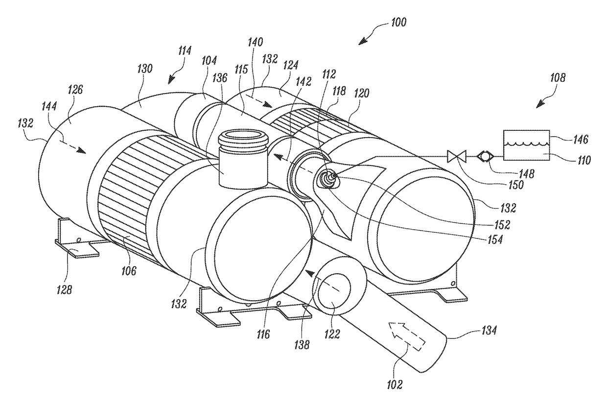
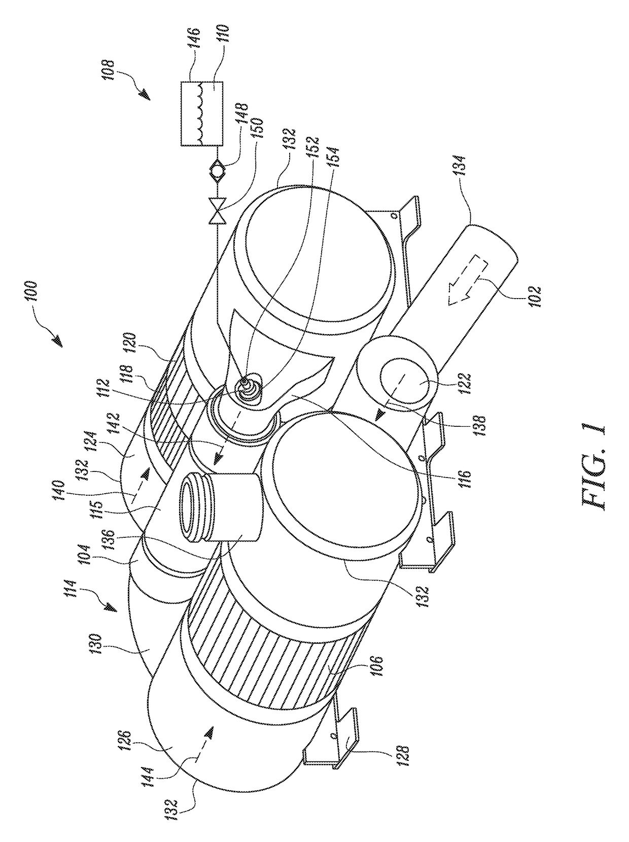
[0022]FIG. 1 illustrates an exhaust after-treatment system 100, according to an embodiment of the present disclosure. The exhaust after-treatment system 100 receives an exhaust flow 102 from an engine (not shown) through an exhaust line 104, connecting the engine to the exhaust after-treatment system 100. The engine may be an internal combustion engine, such as, a reciprocating piston engine or a gas turbine engine. The engine may be fueled by gasoline, diesel fuel, biodiesel, alcohol, natural gas, propane, combinations thereof, or any other combustion fuel known in the art. The engine may further be used to power a machine or any other device, including on-highway trucks or vehicles, off-highway truc...


PUM


Abstract

An injector mounting assembly for supporting an injector is described. The injector mounting assembly includes an upstream wall and a downstream wall coupled to the upstream wall. The injector mounting assembly further includes a thermoelectric cooler coupled to at least one of the upstream wall and the downstream wall. The thermoelectric cooler is disposed in thermal contact with the injector and configured to exchange heat with the injector.

Description

TECHNICAL FIELD[0001]The present disclosure relates to an injector mounting assembly for an exhaust after-treatment system, and more particularly, to an injector mounting assembly having a thermoelectric cooler for cooling an injector mounted thereon.BACKGROUND[0002]In the last few decades, a significant increase in the number of vehicles has been witnessed. The exhaust gases released by the vehicles are harmful in nature and contribute to the already alarming atmospheric pollution. With the advancement of automobile technology, various after-treatment systems are being introduced in the vehicles for treatment of the exhaust gases before leaving the vehicles. Usually, for the treatment and reduction of the exhaust gases, reductants, such as anhydrous ammonia, aqueous ammonia or urea are introduced into a stream of exhaust gases by using injectors.[0003]Such injectors are usually designed for working within a predefined operating range of temperature. However during operation, the in...

Claims


Application Information

Patent Timeline
Patent Type & Authority Patents(United States)
IPC IPC(8): F01N3/02F01N5/02F01N3/20
CPCF01N5/025F01N3/2066F01N2610/1453F01N2610/11F01N3/021F01N3/103F01N2570/18F01N2610/02Y02T10/12
Inventor DENIS, ANDREW M.
Owner CATERPILLAR INC
Features
  • R&D
  • Intellectual Property
  • Life Sciences
  • Materials
  • Tech Scout
  • Unparalleled Data Quality
  • Higher Quality Content
  • 60% Fewer Hallucinations
Learn More