
Active airbearing device

a technology of active airbearing and airbearing rod, which is applied in the direction of bearings, linear bearings, shafts and bearings, etc., can solve the problems of restricting the application of ultra-precision machining or high-speed spindles, and achieve the effects of improving the dynamic stiffness characteristics of airbearing rods, stabilizing airbearing rods, and convenient operation and control

Active Publication Date: 2018-03-20
HUAZHONG UNIV OF SCI & TECH
View PDF16 Cites 1 Cited by
  • Summary
  • Abstract
  • Description
  • Claims
  • Application Information

AI Technical Summary

Benefits of technology

This solution significantly enhances dynamic stiffness characteristics, improves amplitude and frequency bandwidth, stabilizes the airbearing, and effectively suppresses micro-vibrations, making it suitable for demanding applications like ultra-precision machining and high-speed spindles.

Problems solved by technology

Various method of improving the bearing capacity and the stiffness of the airbearing device have been proposed in the prior art, for example, improvements are made to structural shapes, dimensions and other aspects of an orifice and a pressure cavity of airbearing, but improvements to the bearing capacity and the stiffness of such a airbearing device in unit area, which thus restricts its applications in ultra-precision machining or high speed spindle relative to heavy load; in addition, in the prior art, active airbearing is also proposed which uses an actuating element to adjust an open section area of the orifice or the length of the orifice, but such a solution merely has a better effect of adjusting damping characteristics of the airbearing, which is still limited in the effect of adjusting supporting force and stiffness.

Method used


Image

  • Active airbearing device
  • Active airbearing device

Examples


Embodiment Construction

[0027]In order to make the objectives, technical solutions and advantages of the present invention more comprehensible, the present invention is further described below in detail with reference to the accompanying drawings and embodiments. It should be understood that specific embodiments described herein are merely used to explain the present invention instead of being used to limiting the present invention. In addition, technical features involved in various implementations of the present invention described in the following can be combined with each other as long as they do not conflict with each other.

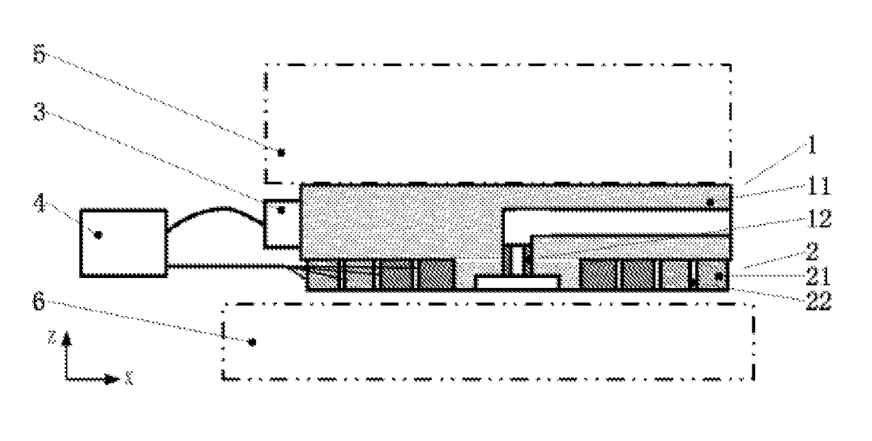
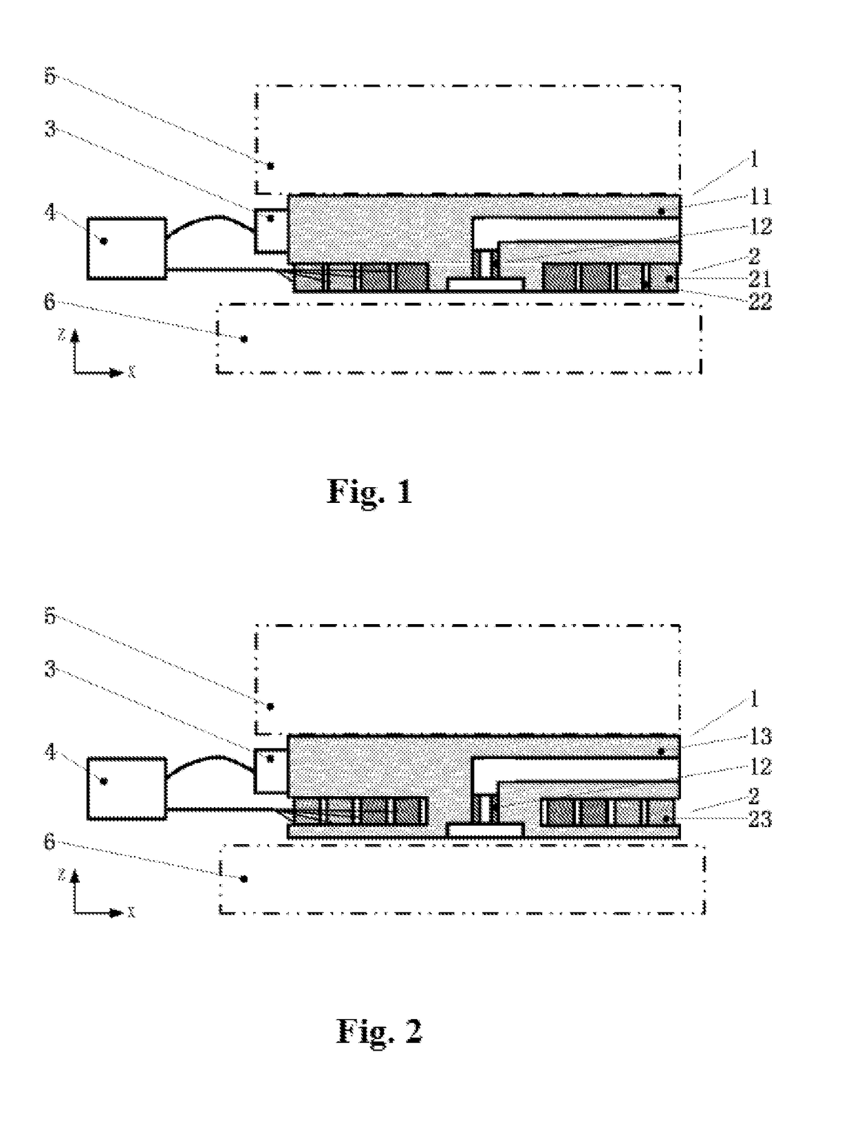
[0028]FIG. 1 is a schematic diagram of a main structure of an active airbearing device constructed according to a first preferred implementation of the present invention. As shown in FIG. 1, the active airbearing device mainly includes a airbearing body 1, a gas film active adjusting unit 2, a support body detection unit 3 and a drive control unit 4, wherein an active adjusting dev...


PUM

PropertyMeasurementUnit
frequencyaaaaaaaaaa
thicknessaaaaaaaaaa
thicknessaaaaaaaaaa

Abstract

The present invention discloses an active airbearing device, including a airbearing body, a gas film active adjusting unit, a support body detection unit and a drive control unit, wherein the support body detection device measures a state of airbearing, the drive control system generates a control signal according to a detection signal, drives and controls the gas film active adjusting device to generate an active action, and dynamically adjusts the form of gas films on a airbearing surface, so as to dynamically adjust pressure distribution of gaps between the gas films of the airbearing device, thereby improving dynamic stiffness characteristics of the airbearing. Through the present invention, the dynamic stiffness characteristics of the airbearing can be improved significantly, and the purpose of stabilizing the airbearing is achieved; in addition, the active airbearing device according to the present invention also has the characteristics of a compact structure, convenient operation and control, and high precision, and thus is especially suitable for occasions such as ultra-precision machining or high speed spindle which has high requirements for dynamic stiffness of support.

Description

TECHNICAL FIELD[0001]The present invention belongs to the field of airbearing device technologies, and in particular, relates to an active airbearing device, which can improve bearing capacity and stiffness, and achieve micron level or even sub-micron level adjustment precision at the same time.BACKGROUND ART[0002]A airbearing device is mainly applied to ultra-precision machining equipment, playing a role of supporting precise moving components. Relative to the traditional mechanical contact guide rail support, there is no direct contact between a airborn moving component and a support member, which avoids contact friction in a moving process, and the moving precision can be improved greatly; therefore, the airbearing device has been widely used in fields of ultra-precision machining, electronics manufacturing, precision measurement, zero-gravity simulation and the like.[0003]A basic form of the airbearing device is as follows: after passing through a pore or slit throttling device,...

Claims


Application Information

Patent Timeline
Patent Type & Authority Patents(United States)
IPC IPC(8): F16C32/06F16C29/00
CPCF16C32/0607F16C29/00F16C32/0614F16C32/067F16C2322/39F16C2233/00F16C29/025
Inventor JIANG, WEICHEN, XUEDONGLUO, XINZENG, LIZHAN
Owner HUAZHONG UNIV OF SCI & TECH
Learn More