
Laminate, non-aqueous electrolyte secondary battery separator including the laminate, and non-aqueous electrolyte secondary battery including the laminate

a non-aqueous electrolyte and secondary battery technology, applied in the direction of electrochemical generators, cell components, cell component details, etc., to achieve the effect of high level of safety

Active Publication Date: 2018-03-20
SUMITOMO CHEM CO LTD
View PDF54 Cites 9 Cited by
  • Summary
  • Abstract
  • Description
  • Claims
  • Application Information

AI Technical Summary

Benefits of technology

The present invention provides a laminate and a non-aqueous electrolyte secondary battery separator that work together to ensure the battery's safety. This is achieved by preventing internal short circuits that can occur due to battery breakage or other factors that compromise safety. The laminate and separator maintain the battery's performance capabilities, such as its rate characteristic and resistance characteristic. This is important for ensuring the battery performs its duties effectively and safely.

Problems solved by technology

However, a non-aqueous electrolyte secondary battery may be heated by a flow of a high current in a case where an internal short circuit or an external short circuit is caused by breakage of the non-aqueous electrolyte secondary battery or breakage of a device in which the non-aqueous electrolyte secondary battery is used.

Method used


Image

  • Laminate, non-aqueous electrolyte secondary battery separator including the laminate, and non-aqueous electrolyte secondary battery including the laminate
  • Laminate, non-aqueous electrolyte secondary battery separator including the laminate, and non-aqueous electrolyte secondary battery including the laminate
  • Laminate, non-aqueous electrolyte secondary battery separator including the laminate, and non-aqueous electrolyte secondary battery including the laminate

Examples


example 1

[0136]The following A layer (porous film) and the following B layer (porous layer) were used to form a laminated porous film (laminate) 1.

[0137]

[0138]Polyethylene serving as polyolefin was used to prepare the porous film 1 serving as a base material.

[0139]That is, 70 parts by weight of ultrahigh molecular weight polyethylene powder (340M, manufactured by Mitsui Chemicals, Inc.) and 30 parts by weight of polyethylene wax (FNP-0115, manufactured by NIPPON SEIRO CO., LTD.) having a weight average molecular weight of 1000 were mixed to obtain mixed polyethylene. To 100 parts by weight of the obtained mixed polyethylene, 0.4 parts by weight of an antioxidant (Irg1010, manufactured by Ciba Specialty Chemicals Inc.), 0.1 parts by weight of an antioxidant (P168, manufactured by Ciba Specialty Chemicals Inc.), and 1.3 parts by weight of sodium stearate were added, and calcium carbonate (manufactured by MARUO CALCIUM CO., LTD.) having an average particle size of 0.1 μm was further added so as...

example 2

[0178]The following A layer and the following B layer were used to form a laminated porous film 2.

[0179]

[0180]A porous film (A layer) made of polyethylene was prepared as in the case of Example 1.

[0181]

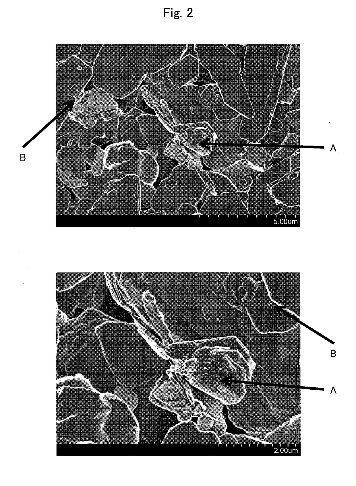
[0182]A coating slip 2 was prepared as in the case of Example 1, except that hydroxyapatite (manufactured by Wako Pure Chemical Industries, Ltd.) was used as inorganic fine particles in Example 2. Note that the hydroxyapatite is fine particles having cleavability.

[0183]

[0184]The laminated porous film 2 in which the B layer was laminated to one side of the A layer was obtained as in the case of Example 1, except that the coating slip 2 was used in Example 2.

[0185]

[0186]Physical properties and the like of the obtained laminated porous film 2 were measured by the method described earlier. Table 1 shows a result of the measurement.

[0187]

[0188]A laminate-type non-aqueous electrolyte secondary battery was prepared as in the case of Example 1, except that the laminated porous film 2 was used...

example 3

[0210]A laminated porous film 3 was obtained as in the case of Example 2, except that in Example 3, a B layer had been formed on both sides of an A layer by coating both sides of the A layer with the coating slip 2.

[0211]

[0212]Physical properties and the like of the obtained laminated porous film 3 were measured by the method described earlier. Table 1 shows a result of the measurement.

[0213]

[0214]A laminate-type non-aqueous electrolyte secondary battery was prepared as in the case of Example 1, except that the laminated porous film 3 was used in Example 3.

[0215]

[0216]A solution resistance of the laminate-type non-aqueous electrolyte secondary battery was calculated as in the case of Example 1. Table 2 shows a result of the calculation.

[0217]

[0218]A cylindrical non-aqueous electrolyte secondary battery was prepared as in the case of Example 1, except that the laminated porous film 3 was used in Example 3.

[0219]

[0220]A 50% breakdown voltage of the cylindrical non-aqueous electrolyte ...


PUM

PropertyMeasurementUnit
thicknessaaaaaaaaaa
thicknessaaaaaaaaaa
thermal conductivityaaaaaaaaaa

Abstract

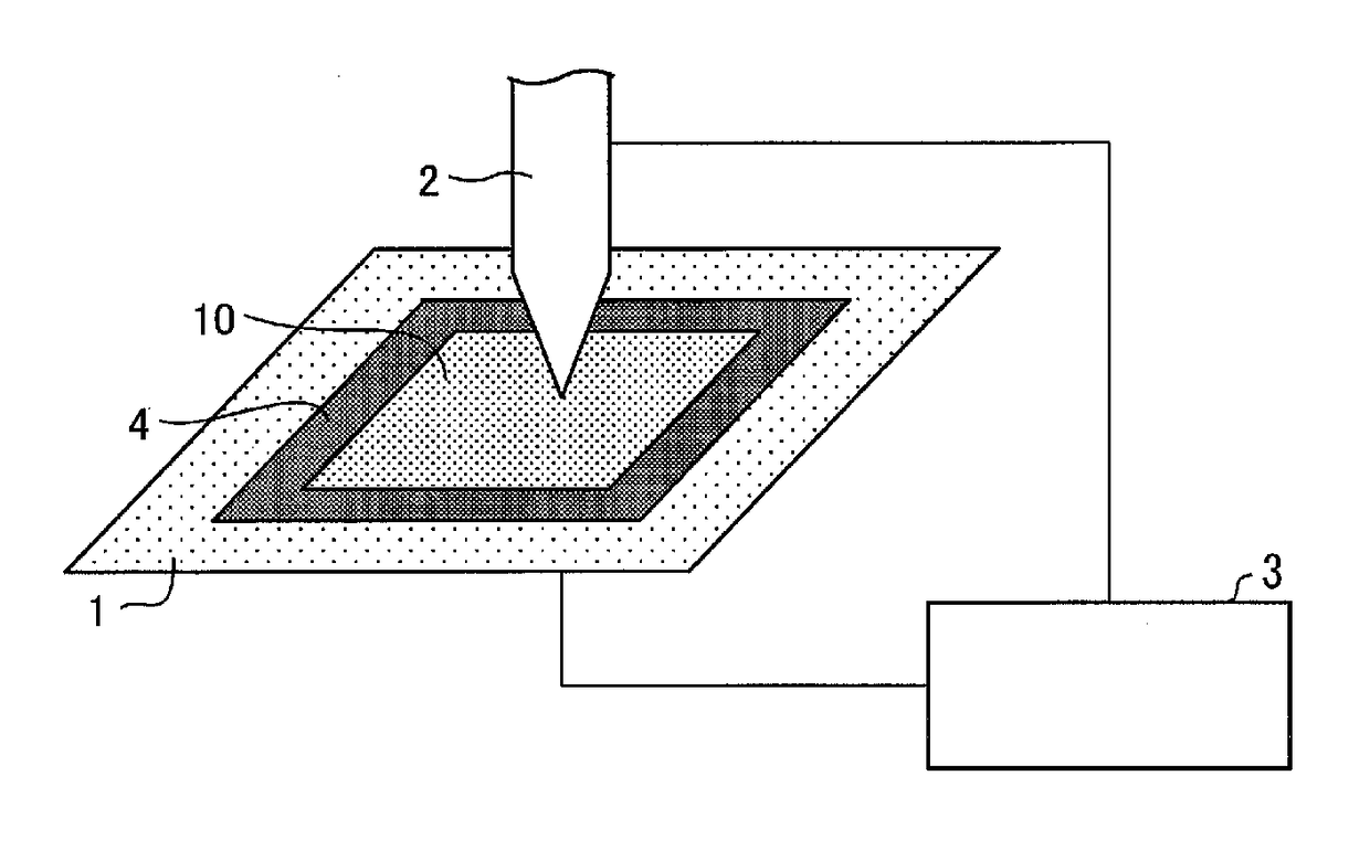
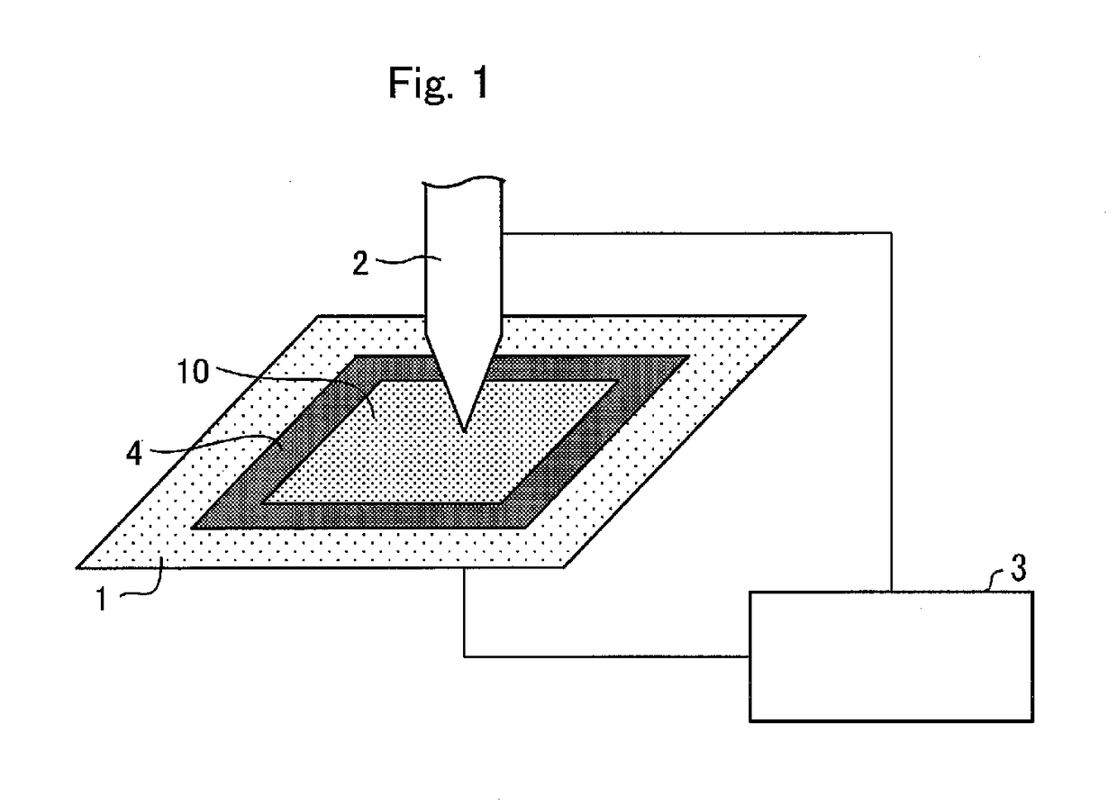
Provided is a laminate which is capable of ensuring a high level of safety by preventing an internal short circuit due to, for example, breakage of a non-aqueous electrolyte secondary battery while maintaining various performance capabilities of the non-aqueous electrolyte secondary battery. A laminate (10) includes: a porous film containing polyolefin as a main component; and a porous layer containing fine particles; the porous layer being laminated to at least one side of the porous film, in an electrical conduction test by nail penetration in which test a displacement in a thickness direction of the laminate (10) during a period from when a dielectric breakdown occurs in the laminate (10) to when the laminate (10) is brought into electrical conduction is measured by use of a nail (2) of N50 specified in JIS A 5508 and under a condition in which the nail (2) descends at a descending speed of 50 μm / min, the displacement being not less than 20 μm and not more than 200 μm.

Description

CROSS REFERENCE TO RELATED APPLICATIONS[0001]This application is a National Stage of International Application No. PCT / JP2015 / 070730 filed Jul. 21, 2015, claiming priority based on Japanese Patent Application No. 2014-209415, filed Oct. 10, 2014, the contents of all of which are incorporated herein by reference in their entirety.TECHNICAL FIELD[0002]The present invention relates to a laminate, a non-aqueous electrolyte secondary battery separator including the laminate, and a non-aqueous electrolyte secondary battery including the laminate.BACKGROUND ART[0003]A non-aqueous electrolyte secondary battery typified by a lithium ion secondary battery has a high energy density. Thus, a non-aqueous electrolyte secondary battery is currently being widely used as a battery for use in devices such as a personal computer, a mobile phone, and a mobile information terminal.[0004]However, a non-aqueous electrolyte secondary battery may be heated by a flow of a high current in a case where an inte...

Claims


Application Information

Patent Timeline
Patent Type & Authority Patents(United States)
IPC IPC(8): H01M2/16B32B5/32B32B27/32C09D1/00B32B27/20B32B15/085B32B15/20H01M50/414H01M50/417H01M50/42H01M50/423H01M50/426H01M50/429H01M50/431H01M50/451H01M50/457
CPCH01M2/1686B32B5/32H01M2/166B32B2255/10B32B2255/06B32B2255/26B32B2264/10B32B2264/102B32B2264/108B32B2264/12B32B2307/58B32B2307/718B32B2307/732B32B2457/10B32B2571/00C09D1/00H01M2/1646H01M2/1653B32B15/085B32B15/20B32B27/205B32B27/32B32B2255/20C08K3/26C08K3/34C08K2003/265Y02E60/10H01M50/431H01M50/417H01M50/429H01M50/457H01M50/451H01M50/414H01M50/423H01M50/42H01M50/426B32B27/18H01M10/0525B32B2266/025H01M50/446H01M50/449H01M50/411
Inventor YOSHIMARU, CHIKAEKURAKANE, KOSUKEMURAKAMI, CHIKARA
Owner SUMITOMO CHEM CO LTD
Learn More