Balloon catheter

a balloon catheter and catheter tube technology, applied in the field of balloon catheters, can solve the problems of difficulty in breathing, pain in the chest, and difficulty in delivering balloon catheters, and achieve the effects of facilitating surgical procedures, reducing the diameter of the shaft, and improving pushability

Active Publication Date: 2018-03-27
IND ACADEMIC COOP FOUND YONSEI UNIV
View PDF25 Cites 1 Cited by
  • Summary
  • Abstract
  • Description
  • Claims
  • Application Information

AI Technical Summary

Benefits of technology

[0024]In accordance with the present invention, the first shaft and the second shaft are connected coaxially, and the expansion lumen and the guide wire lumen are formed in each of the shafts. Accordingly, there are advantages in that a surgical procedure becomes facilitated and pushability is improved because the diameter of the shaft is generally reduced.
[0025]Furthermore, there is an advantage in that the time taken to expand and contract a balloon can be reduced because the diameter of the expansion lumen is relatively increased due to only one lumen present in a single shaft.

Problems solved by technology

If the blood is not sufficiently supplied to the heart muscle, a pain in the chest, a difficulty in breathing, and other symptoms are generated depending on a degree thereof.
However, the aforementioned prior art has the following problems.
The conventional balloon catheter is problematic in that the diameter of the shaft 1 is generally increased because the guide wire lumen 4 and the expansion lumen 5 are overlapped with each other and formed in the shaft 1.
If the diameter of the shaft 1 is increased as described above, pushability is lowered when a surgical operator performs a surgical procedure on the catheter, making the surgical procedure difficult.
In particular, there is a problem in that a surgical procedure for a tortuous blood vessel, such as the heart blood vessel, is difficult.
Furthermore, if the guide wire lumen 4 and the expansion lumen 5 are formed together, there is a problem in that the time taken to expand and contract the balloon 2 becomes long because the diameter of the expansion lumen 5 is inevitably relatively reduced.

Method used


Image

  • Balloon catheter
  • Balloon catheter
  • Balloon catheter

Examples


Embodiment Construction

[0032]Hereinafter, an embodiment of a balloon catheter according to the present invention is described in detail with reference to the accompanying drawings. In terms used herein, the ‘front’ means the bottom on the basis of FIG. 2, that is, the direction along which the balloon catheter is inserted, and ‘the rear’ means the top on the basis of FIG. 2, that is, the direction opposite the direction along which the balloon catheter is inserted. Furthermore, a term ‘front end’ means an end that is placed at the front in the balloon catheter, and a term ‘rear end’ means an end that is placed at the back in the balloon catheter.

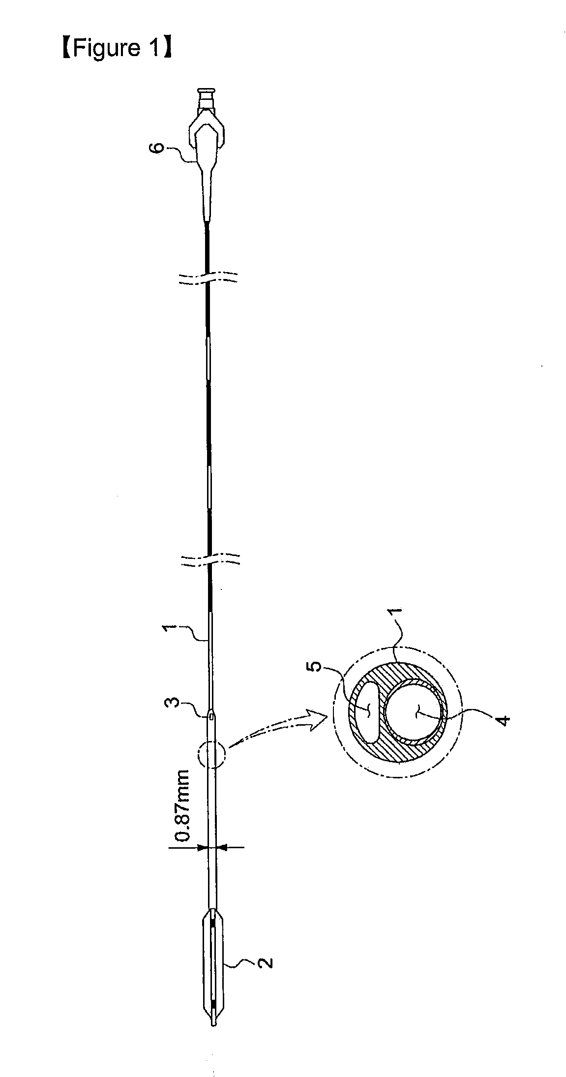
[0033]FIG. 2 is a side view showing a balloon catheter in accordance with an embodiment of the present invention.

[0034]Referring to FIG. 2, the balloon catheter according to the present invention basically includes a first shaft 10; a balloon 12 attached to the front end of the first shaft 10; and a second shaft 20 coaxially extended from the front end of the firs...


PUM


Abstract

The present invention relates to a balloon catheter. The invention comprises: a first shaft; an expandable balloon which is attached to the front end of the first shaft; an expandable lumen which is formed inside the first shaft and to which a liquid required for expanding the balloon is provided; a second shaft which extends from the front end of the first shaft to which the balloon is attached and has a wire hole through which a guide wire passes; and a guide wire lumen, which is formed inside the second shaft and through which the guide wire passes. According to the invention, the first and second shafts are coaxially connected and the expandable lumen and the guide wire lumen are respectively formed in each shaft in order to reduce the overall diameter of the shaft, thereby facilitating surgery and improving pushability.

Description

CROSS-REFERENCE TO RELATED APPLICATION[0001]This application claims priority to and the benefit of Korean Patent Application No. 10-2011-0083548, filed Aug. 22, 2011, and Korean Patent Application No. 10-2012-0089980, filed Aug. 17, 2012, the disclosure of which is incorporated herein by reference in its entirety.TECHNICAL FIELD[0002]The present invention relates to a balloon catheter and, more particularly, to a balloon catheter in which an expansion lumen to which liquid for the expansion of a balloon is supplied and a guide wire lumen through which a guide wire passes are configured not to overlap with each other and the diameter of a shaft is reduced, thereby enabling easy transfer to a limited space of a guide catheter, smoothing the injection of a contrast medium when a surgical procedure is performed since a sufficient space can be secured, and capable of improving pushability by which two or more balloon catheters can enter at the same time.BACKGROUND ART[0003]In general, a ...

Claims


Application Information

Patent Timeline
Patent Type & Authority Patents(United States)
IPC IPC(8): A61M25/10A61M5/00A61M25/00
CPCA61M5/007A61M25/10A61M2025/0059A61M2025/0183A61M2025/1056A61M25/09A61M25/01
Inventor JANG, YANG SOOHONG, MYEONG KIKIM, BYEONG KEUK
Owner IND ACADEMIC COOP FOUND YONSEI UNIV
Why Eureka
Try Eureka