
Refining used motor oil through successive hydrotreating processes

a technology of hydrotreating process and used motor oil, which is applied in the direction of hydrocarbon distillation, vacuum distillation, lubricating oil distillation, etc., can solve the problems of process fallout and large majority of used oil is improperly disposed, and achieve the effect of improving the economic efficiency of the process

Active Publication Date: 2018-04-03
AIR PROD & CHEM INC
View PDF7 Cites 8 Cited by
  • Summary
  • Abstract
  • Description
  • Claims
  • Application Information

AI Technical Summary

Benefits of technology

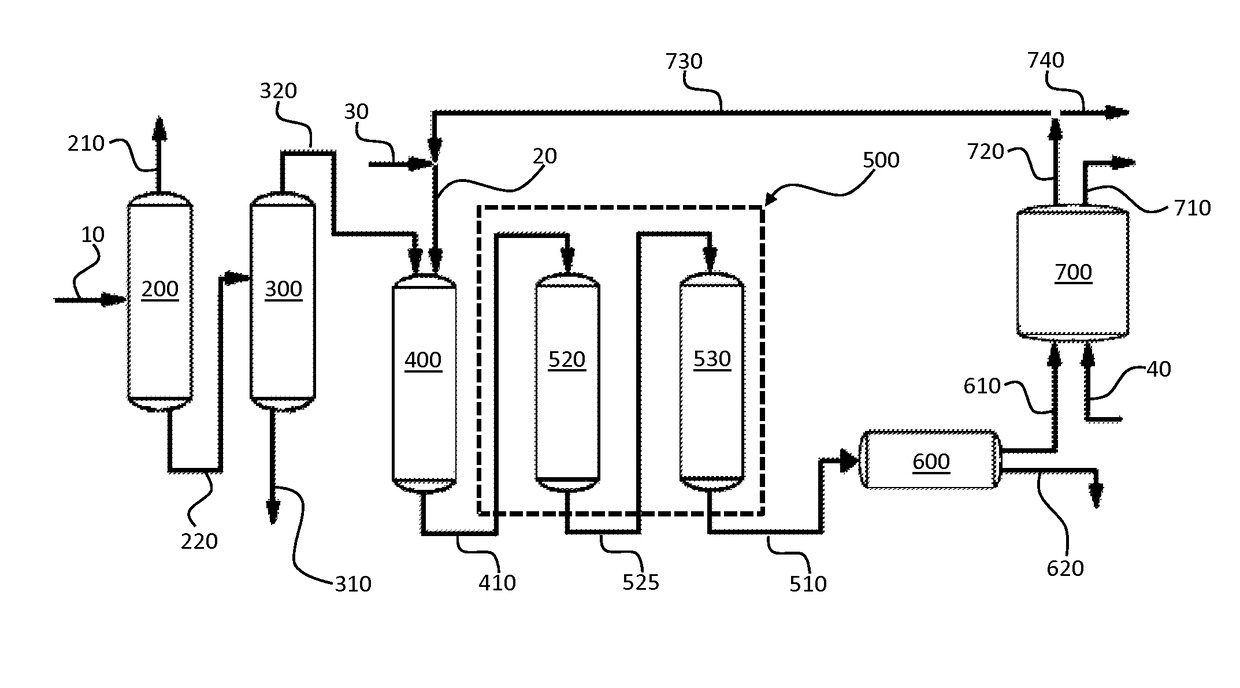
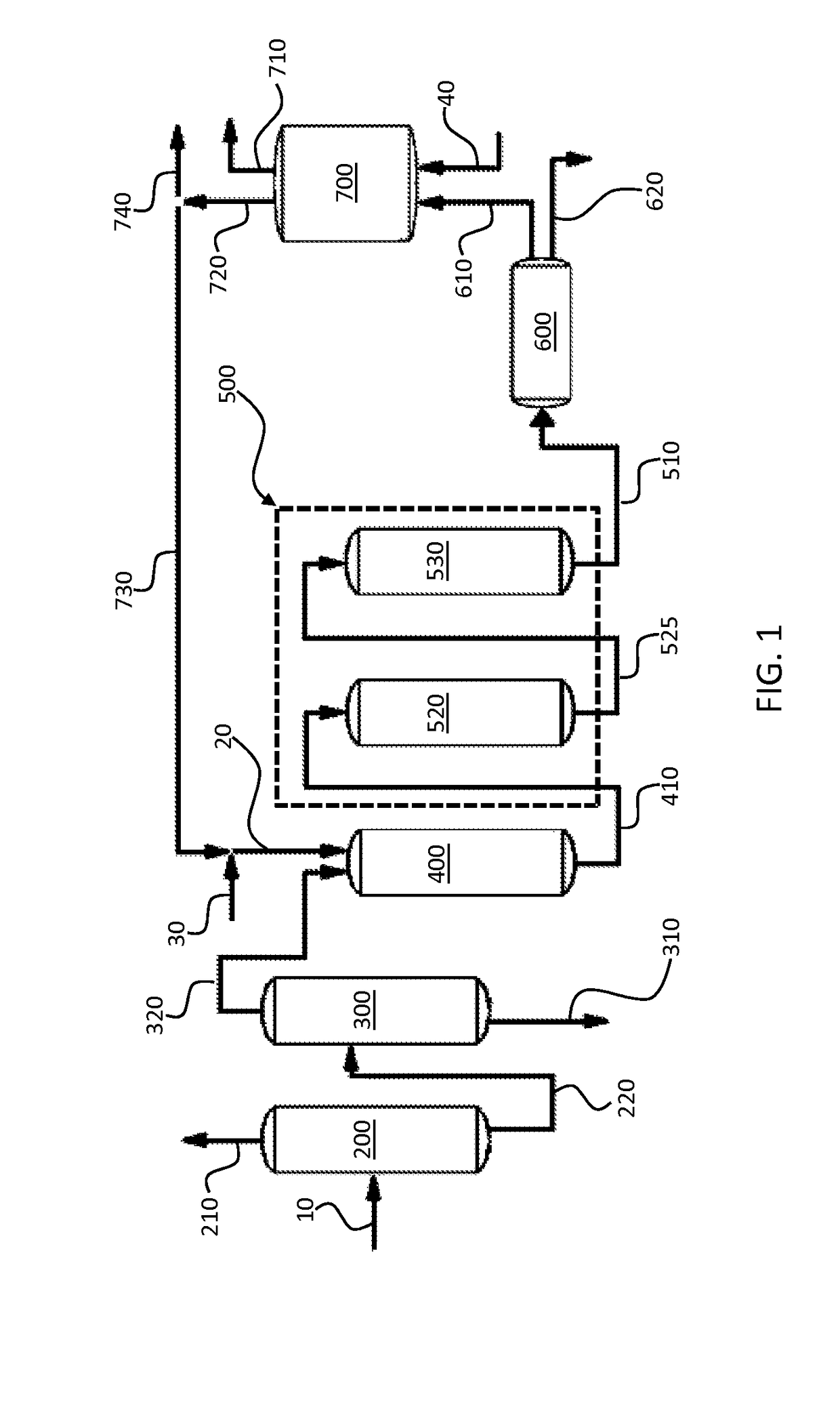
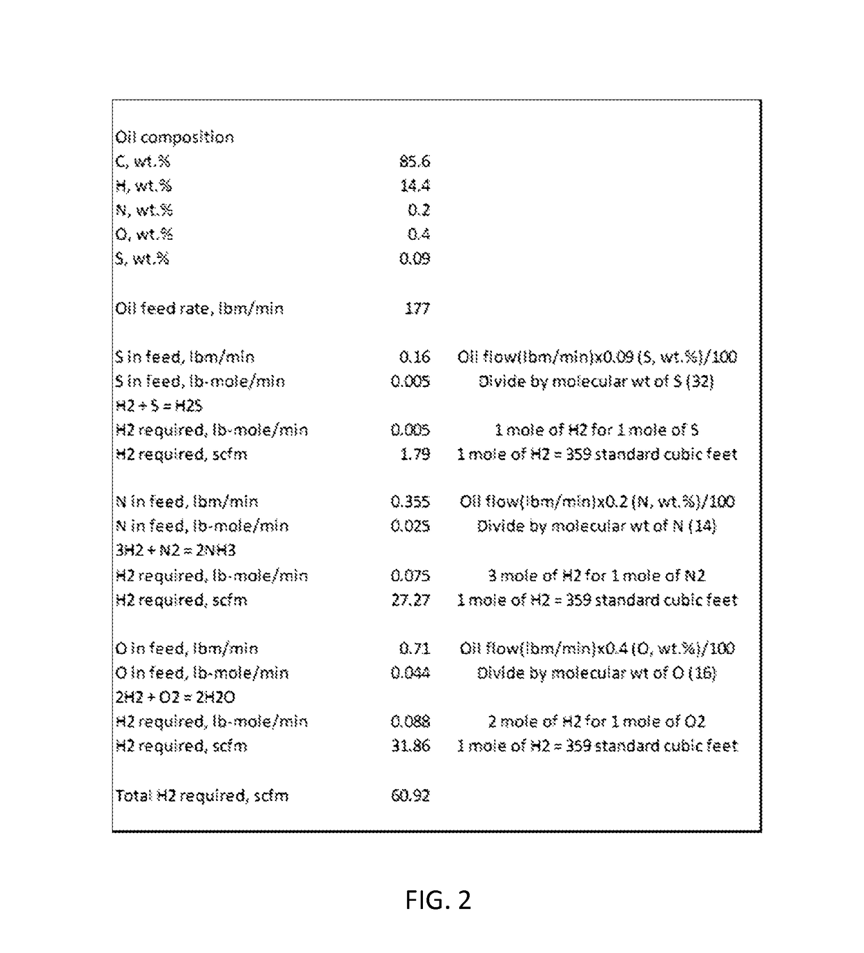
[0006]To improve the economic efficiency of the process, a portion of the hydrogen may be recovered after the one or more additional hydrotreating reactors and recycled back into the first hydrotreating reactor. To avoid accumulation of impurities, a portion of the recovered hydrogen may be purged before recycling the remaining portion back into the first hydrotreating reactor. To maintain the flow rate of total hydrogen into the first reactor, a fresh hydrogen stream may be added to the recycled hydrogen stream to replace hydrogen consumed by the reaction and hydrogen lost in the purged portion of the recovered hydrogen. The flow rate of the fresh hydrogen is at least in excess of the stoichiometric amount of hydrogen required to remove most of the heteroatom impurities from the unrefined gasoil, preferably approximately 1.5, approximately 2.0, or approximately 2.5 times greater than the required amount, depending on the volume of the purged portion.

Problems solved by technology

Millions of gallons of used motor oil (or lubricating oil) are generated each day in the US, and a vast majority of used oil is improperly disposed each year.
Due to the costs associated with recovery of solvent, inability of clays to remove modern additives, cost associated with disposal of spent clays and chemicals, and production of re-refined oil with inconsistent quality, such processes have fallen out of favor.

Method used


Image

  • Refining used motor oil through successive hydrotreating processes
  • Refining used motor oil through successive hydrotreating processes
  • Refining used motor oil through successive hydrotreating processes

Examples


example 1

[0024]A gasoil having the elemental composition and metal impurity contents listed below in Tables 1 and 2, respectively, were hydrotreated in four reactors operated in series.

[0025]

TABLE 1ElementCHNOSConcentration85.3 wt. %14.2 wt. % 0.1 wt. %0.6 wt. %980 ppm

[0026]

TABLE 2ElementCaMgNaSiZnPBConc. (ppm)0.50.20.8170.43010

[0027]The first reactor was packed with commercially available pre-sulfided Co—Mo catalyst supported on alumina and operated at a temperature of 308° C. The second reactor was also packed with commercially available pre-sulfided Co—Mo catalyst supported on alumina and operated at a temperature of 303° C. temperature. The third reactor was loaded with commercially available pre-sulfided Ni—Mo catalyst supported on alumina and operated at a temperature of 301° C. The fourth and last reactor was loaded with commercially available pre-sulfided Ni—Mo catalyst supported on alumina and operated at a temperature of 299° C. The oil was hydrotreated at approximately 1,200 psig ...

example 2

[0034]A gasoil having the elemental composition and metal impurity contents listed below in Tables 5 and 6, respectively, were hydrotreated in three reactors operated in series.

[0035]

TABLE 5ElementCHNOSConcentration85.6 wt. %14.4 wt. %0.2 wt. %0.4 wt. %900 ppm

[0036]

TABLE 6ElementCaMgNaSiZnPConc. (ppm)100.44844

[0037]The first reactor was packed with commercially available pre-sulfided Ni—Mo catalyst and operated at a temperature of 235° C. The second reactor was also packed with commercially available pre-sulfided Ni—Mo catalyst and operated at a temperature of 257° C. temperature. The third and last reactor was loaded with commercially available pre-sulfided Co—Mo catalyst and operated at a temperature of 312° C. The gasoil was hydrotreated at approximately 1,175 psig pressure with 5865 standard m3 per m3 of oil of an impure recycled hydrogen stream combined with 18 standard m3 per m3 of oil of a fresh hydrogen stream. Because the recycled hydrogen stream contains less 100% hydrogen...

example 3

[0043]The gasoil hydrotreating process described in Example 2 was repeated using the same feed gasoil, same three reactors operated in series, and the same temperatures as in Example 2 in all three reactors. The flow rate of fresh hydrogen was increased to provide a ratio of fresh hydrogen flow rate to stoichiometric flow rate of hydrogen required for heteroatom removal of approximately 1.8. The oil was hydrotreated at approximately 1,175 psig pressure with 5865 standard m3 per m3 of oil of an impure recycled hydrogen stream combined with 27 standard m3 per m3 of oil of a fresh hydrogen stream. Because the recycled hydrogen stream contains less 100% hydrogen, the total hydrogen flow rate is less than the combined total flow rate of 5892 m3. The ratio of fresh hydrogen flow rate to stoichiometric flow rate of hydrogen required to remove sulfur, nitrogen and oxygen compounds was approximately 1.77. The gasoil feed rate was such that it provided a LHSV of approximately 0.8 hr-1. After ...


PUM

PropertyMeasurementUnit
temperatureaaaaaaaaaa

Abstract

A method for refining used motor oil using two or more hydrotreating reactors arranged in series. The used motor oil may be vacuum distilled to produce an unrefined gasoil. The unrefined gasoil may then be hydrotreated in a first hydrotreating reactor with hydrogen operated at a temperature ranging from approximately 245° C. to approximately 260° C. to produce a hydrotreated gasoil. The hydrogen may comprise a mixture of fresh hydrogen and recycled hydrogen recovered from the last of the two or more hydrotreating reactors. The hydrotreated gasoil may then be hydrotreated in one or more additional hydrotreating reactors operated at temperatures ranging from approximately 260° C. to approximately 330° C. to produce a refined gasoil. The first hydrotreating reactor may remove a substantial portion of metallic impurities from the unrefined impurities, while the one or more additional hydrotreating reactors remove a substantial portion of heteroatom impurities from the unrefined gasoil.

Description

TECHNICAL FIELD[0001]The present invention relates generally to refining used oil and, more particularly, to refining used motor oil through a process including two or more hydrotreating steps.BACKGROUND[0002]Millions of gallons of used motor oil (or lubricating oil) are generated each day in the US, and a vast majority of used oil is improperly disposed each year. Lubricating oil, which is essentially a mixture of paraffinic, naphthenic, and aromatic hydrocarbons, is stable and does not degrade or wear out. However, additives, including both inorganic and organometallic additives, that are added to enhance motor oil, such as to improve its lubricating and anti-wear properties, oxidize, deplete, and wear out. Consequently, used motor oil needs to be treated to remove worn-out additives prior to recycling it as a feedstock for preparing fresh motor oil.[0003]Refining of used motor oil began in earnest in the 1970s. Early processes involved removing contaminants such as dirt, water, f...

Claims


Application Information

Patent Timeline
Patent Type & Authority Patents(United States)
IPC IPC(8): C10G65/04C10G67/02C10G67/06C10G7/00C10G7/06
CPCC10G65/04C10G7/003C10G7/06C10G2300/1074C10G2300/1007C10G2300/1059C10G67/02
Inventor GARG, DIWAKARLEBRECHT, TIMOTHY D.
Owner AIR PROD & CHEM INC
Learn More