Variable capacitance device and communication apparatus
a technology of variable capacitance and capacitance device, which is applied in the direction of electrical apparatus, circuit arrangement, structure fixed capacitor combination, etc., can solve the problems of deteriorating esd resistance breaking of variable capacitance device, and achieve high esd resistance
- Summary
- Abstract
- Description
- Claims
- Application Information
AI Technical Summary
Benefits of technology
Problems solved by technology
Method used
Image


Examples
first preferred embodiment
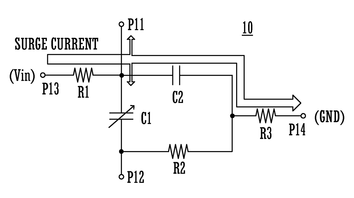
[0031]A variable capacitance device 10 according to a first preferred embodiment of the present invention will be described. FIG. 1 is a circuit diagram illustrating an inside of the variable capacitance device 10. The variable capacitance device includes a ferroelectric capacitor C1, a capacitor C2, resistances R1 to R3, input / output terminals P11 and P12, a control terminal P13, and a ground terminal P14. The resistance R1 corresponds to a first resistance. The resistance R2 corresponds to a second resistance. The resistance R3 corresponds to a third resistance.
[0032]A first end of the ferroelectric capacitor C1 is connected to the control terminal P13 via the resistance R1, and also connected to a first end of the capacitor C2 and the input / output terminal P11. A second end of the ferroelectric capacitor C1 is connected to a first end of the resistance R2 and the input / output terminal P12. A second end of the capacitor C2 is connected to a second end of the resistance R2, and its...
second preferred embodiment
[0041]A variable capacitance device 30 according to a second preferred embodiment of the present invention will be described. FIG. 3 is a circuit diagram illustrating an inside of the variable capacitance device 30. The variable capacitance device 30 includes ferroelectric capacitors C11 to C16, a capacitor C2, resistances R11 to R19, input / output terminals P11 and P12, a control terminal P13, and a ground terminal P14.
[0042]The ferroelectric capacitors C11 to C16 are connected in series in this order between the input / output terminals P11 and P12. A connection point between the ferroelectric capacitor C11 and the ferroelectric capacitor C12 is connected to a first end of the resistance R19 via the resistance R12, and also connected to a first end of the resistance R18 via the capacitor C2. A connection point between the ferroelectric capacitor C13 and the ferroelectric capacitor C14 is connected to the first end of the resistance R19 via the resistance R14. A connection point betwe...
third preferred embodiment
[0055]A communication apparatus 101 according to a third preferred embodiment of the present invention will be described. FIG. 5 is a circuit diagram illustrating the communication apparatus 101. The communication apparatus 101 includes an RFIC 11, a control IC 12, an antenna coil 13, a control voltage application circuit 14, and the variable capacitance device 30 according to the second preferred embodiment.
[0056]The RFIC 11 includes an IO terminal 11P of GPIO (General Purpose Input / Output). Similarly, the control IC 12 includes an IO terminal 12P of GPIO.
[0057]The RFIC 11 performs transformation between a base band signal and a high-frequency signal. The control IC 12 controls the RFIC 11 to input / output data containing communication data.
[0058]The control voltage application circuit 14 divides a voltage inputted to the input terminal 14P to generate a control voltage, and applies this control voltage to the variable capacitance device 30.
[0059]A parallel circuit including the var...
PUM
 Abstract
Description
Claims
Application Information