
Intra-uterine insertion device

a technology for intrauterine devices and insertion devices, which is applied in the field of intrauterine device insertion devices, can solve the problems of high demand and cost for quality control, inefficient handling of existing inserters, and high production cost, and achieve the effect of increasing the resistance to sliding

Active Publication Date: 2018-04-24
ODYSSEA PHARMA S P R L
View PDF14 Cites 6 Cited by
  • Summary
  • Abstract
  • Description
  • Claims
  • Application Information

AI Technical Summary

Benefits of technology

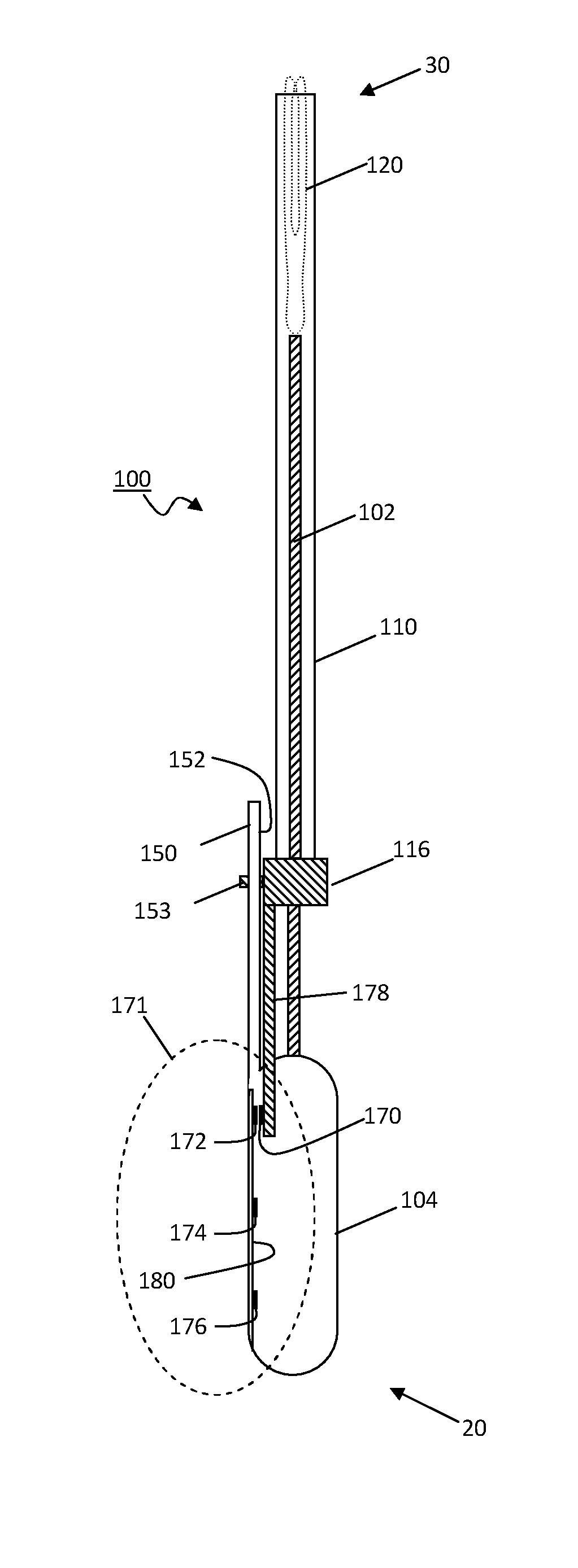
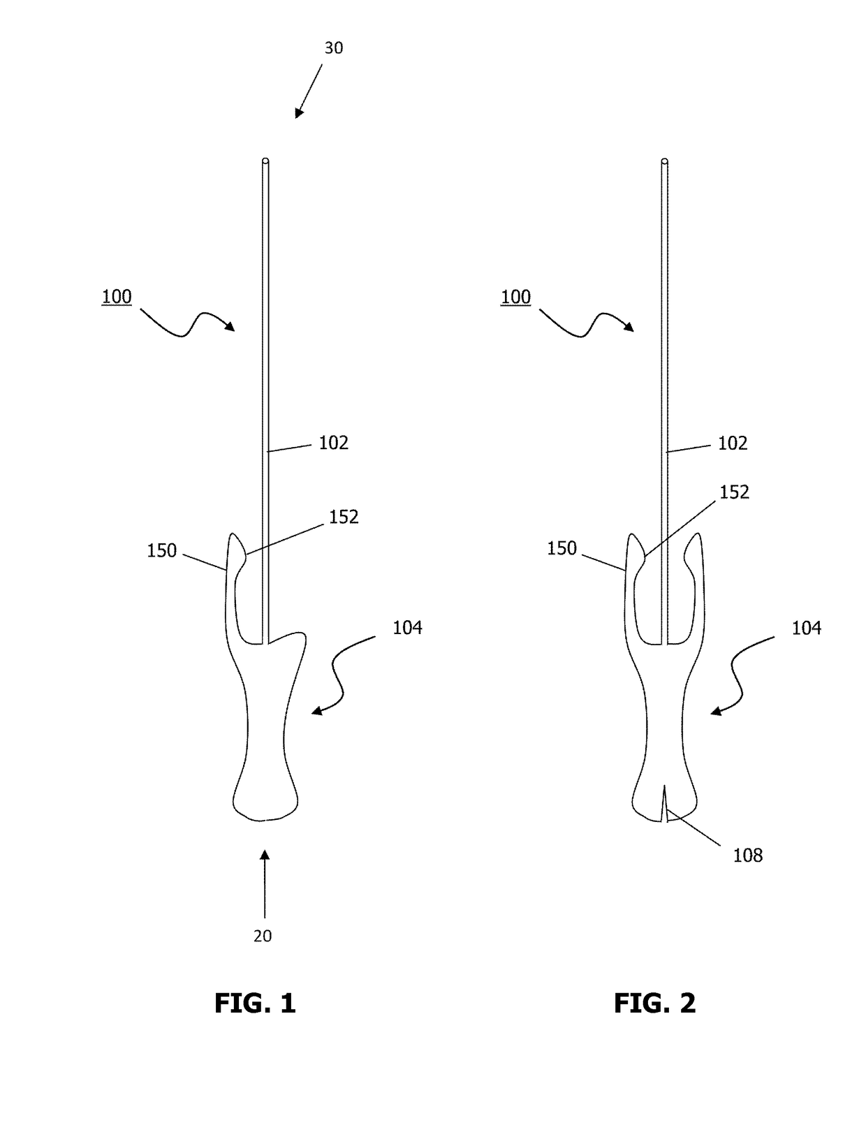
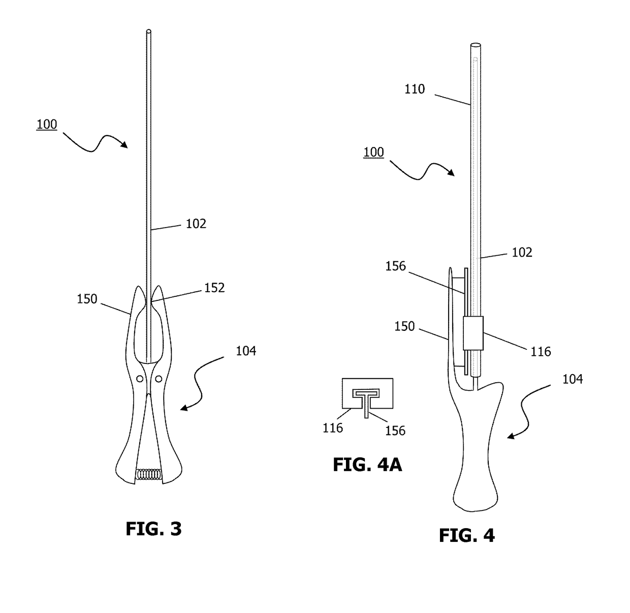
[0022]The friction contact surface (152) may comprise a longitudinal guiding rail (156), wherein the protective tube (110) is provided at the proximal (20) end with a cuff (116), and wherein the longitudinal guiding rail (156) and the cuff (116) are slidably connected. The longitudinal member (150) may comprise a longitudinal guiding slot (151) and the cuff (116) disposed with a T-shaped protrusion (153), slot along which the T-shaped protrusion (153) slidably engages, allowing the protective tube (110) to slide relative to the longitudinal member (150). The friction contact surface (152) and / or the surface of the plunger (102) may comprise serrations (154), configured to improve resistance to sliding of the protective tube (110) relative to the plunger (102) upon frictional engagement.
[0028]the protective tube (110) may be attached in fixed relation to a third discrete contact element (170′) and the plunger attached in fixed relation to a fourth discrete contact element (174), the third (170′) and fourth (174) discrete contact elements being in slidable relation to each other and configured such that they engage together so increasing the resistance to sliding of the protective tube (110) relative to the plunger (102) selectively at a second discrete position (P2) which corresponds to a location of the protective tube (110) where it covers at least part of the IUD (120) central rod, and the wings are unfolded when the central rod (124) of the IUD (120) is engaged with the distal (30) end of the plunger (102).

Problems solved by technology

However, because of the delicate nature of the insertion procedure, existing inserters are often inefficient in handling, which is mainly due to the various moving parts.
Production costs are relatively high because of the different parts that need to be assembled correctly.
Furthermore, the more complicated the device assembly, the higher the demands and costs are for quality control.
However, these stops are discrete and only tailored to the insertion of one particular IUD with a specific size and shape.
Therefore, the same inserter cannot be used to insert an IUD that differs in shape or size.

Method used


Image

  • Intra-uterine insertion device
  • Intra-uterine insertion device
  • Intra-uterine insertion device

Examples


Embodiment Construction

[0088]Unless defined otherwise, all technical and scientific terms used herein have the same meaning as is commonly understood by one of skill in the art. All publications referenced herein are incorporated by reference thereto.

[0089]The articles ‘a’ and ‘an’ are used herein to refer to one or to more than one, i.e. to at least one of the grammatical object of the article.

[0090]Throughout this application, the term ‘about’ is used to indicate that a value includes the standard deviation of error for the device or method being employed to determine the value.

[0091]The recitation of numerical ranges by endpoints includes all integer numbers and, where appropriate, fractions subsumed within that range (e.g. 1 to 5 can include 1, 2, 3, 4 when referring to, for example, a number of elements). The recitation of end points also includes the end point values themselves (e.g. from 1.0 to 5.0 includes both 1.0 and 5.0).

[0092]Reference throughout this specification to “one embodiment” or“an em...


PUM


Abstract

The present invention relates to an inserter (100), having a proximal (20) and distal (30) end, for inserting and positioning an intra-uterine device (IUD) (120), which is attached to a withdrawal string (130), said inserter (100) comprising: a) a plunger (102), having a central longitudinal axis, configured for slidable mounting of a hollow protective tube (110), the distal (30) end of the plunger (102) being configured for dismountable connection with the IUD (120), which protective tube (110) is configured to slidably cover the IUD (120); b) a handle (104), which is attached to the proximal (20) end of the plunger (102); and c) a longitudinal member (150) that forms part of the handle (104), which extends in the distal (30) direction with respect to the plunger (102), which longitudinal member (150) contains a friction contact surface (152) against which the protective tube (110) can frictionally engage, wherein the frictional engagement of the friction contact surface (152) against the protective tube (110) is manually actuatable and wherein the frictional engagement of the friction contact surface (152) against the protective tube (110) increases resistance to sliding of the protective tube (110) relative to the plunger (102).

Description

CROSS-REFERENCE TO RELATED APPLICATIONS[0001]This application is the U.S. National Phase under 35 U.S.C. § 371 of International Application PCT / EP2011 / 068364, filed Oct. 20, 2011, which claims priority to U.S. Provisional Application 61 / 408,316, filed Oct. 29, 2010, EP 11158273.0, filed Mar. 15, 2011 and U.S. Provisional Application 61 / 453,026 filed Mar. 15, 2011.FIELD OF THE INVENTION[0002]The invention relates to apparatuses and methods for inserting intra-uterine devices (IUDs).BACKGROUND OF THE INVENTION[0003]Hormonal or copper intra-uterine devices (IUDs) or intra-uterine systems (IUSs) are used as a common method of anti-conception and / or for treatment of menorrhagia and / or for treatment of other conditions. The term IUD (intra-uterine device) will be used herein to refer to both IUDs and IUSs.[0004]IUDs are commonly T-shaped, having an elongated member (from hereon called the central rod) having at one end a transverse member comprising two wings. The wing tips (also known as...

Claims


Application Information

Patent Timeline
Patent Type & Authority Patents(United States)
IPC IPC(8): A61F6/18A61F6/06A61B17/12A61F6/14
CPCA61F6/18A61F6/06A61F6/14A61F6/144A61B2017/1205
Inventor FRANKENNE, FRANCISGERKENS, VINCENT
Owner ODYSSEA PHARMA S P R L
Learn More