Driveline system with nested loop damping control

Active Publication Date: 2018-04-24
GM GLOBAL TECH OPERATIONS LLC
View PDF3 Cites 0 Cited by
  • Summary
  • Abstract
  • Description
  • Claims
  • Application Information

AI Technical Summary

Benefits of technology

The patent describes a method for controlling a driveline system that includes an electric machine and a rotating axle. The system may experience high-frequency vibrations, which can be actively damped using a nested loop control system. The control system includes an outer control loop and an inner control loop, with the inner control loop operating at a faster sampling rate than the outer control loop. The method involves generating a commanded torque using the nested control loop, and controlling the electric machine to rotate the axle and load. The system can also include a hybrid control processor and a motor control processor, with different sampling rates for the outer and inner control loops. The technical effect of this patent is to provide an effective solution for damping high-frequency driveline oscillations in a driveline system.

Problems solved by technology

Undesirable driveline oscillation may result due to interaction of the rotating electric machine and stiffness of the drive axle to which the electric machine is coupled.

Method used


Image

  • Driveline system with nested loop damping control
  • Driveline system with nested loop damping control
  • Driveline system with nested loop damping control

Examples


Embodiment Construction

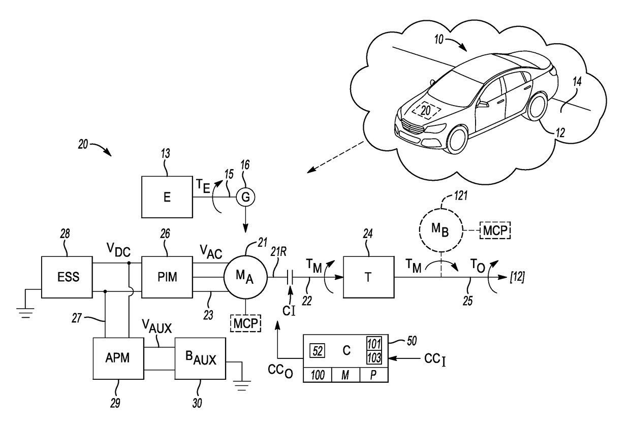
[0016]Referring to the drawings, wherein like reference numbers refer to the same or similar components throughout the several views, and beginning with FIG. 1, an example vehicle 10 includes a powertrain 20 having a driveline system 11. The driveline system 11 includes one or more torque generating devices, at least one axle, and a driven load coupled to the axle(s). In the illustrated embodiment, the load includes drive wheels 12 in rolling frictional contact with a road surface 14. The driveline system 11 includes an electric machine (MA) 21 having a rotor shaft 21R that is coupled to an input shaft 22 of a transmission (T) 24 via an input clutch CI. The transmission 24 may include one or more planetary gear sets (not shown) or other geared arrangements suitable for transferring an output torque (arrow TO) to an output shaft / drive axle 25, and from the drive axle 25 to the road wheels 12. Some embodiments may also include another electric machine (MB) 121 coupled to the input sha...


PUM


Abstract

A driveline system includes a drive axle coupled to a load, an electric machine, and a control system. The electric machine is responsive to a commanded torque, has a rotor shaft coupled to the axle, and produces an output torque that rotates the axle and load to produce driveline oscillation at a high resonant frequency. The control system generates the commanded torque using a nested control loop architecture in which an outer control loop operates at a sampling rate that is below a critical rate necessary for controlling the resonant frequency, and an inner control loop operates at a sampling rate that is above the critical rate. The inner loop determines a modified torque command and acceleration value in response to a commanded torque from the outer loop. The electric machine is thereafter controlled via the commanded torque.

Description

INTRODUCTION[0001]A driveline delivers torque from a torque generating device to a coupled load via a rotatable shaft or axle. For instance, a vehicular driveline system may include one or more high-voltage electric machines coupled to a drive axle via a geared power transmission arrangement. Torque from the electric machines is imparted to the drive axle to power the load, such as by rotating a set of drive wheels, turning an electric generator to generate electricity, or rotating a propeller shaft. The electric machines may act alone or in conjunction with an internal combustion engine or another torque generating device. Undesirable driveline oscillation may result due to interaction of the rotating electric machine and stiffness of the drive axle to which the electric machine is coupled. Depending on the structure and dynamics of the driveline system, such driveline oscillation may occur at a relatively high resonant frequency.SUMMARY[0002]A driveline system is disclosed herein ...

Claims


Application Information

Patent Timeline
IPC IPC(8): B60W20/15B60K6/26
CPCB60W20/15B60K6/26Y10S903/906B60W2710/083B60Y2200/92B60Y2300/22B60W10/08B60W30/20B60K6/46B60W2050/0019B60W2710/081Y02T10/62Y02T10/72
Inventor YANG, JIEMORRIS, ROBERT L.LIU, CHIA-SHANGSON, YO CHAN
Owner GM GLOBAL TECH OPERATIONS LLC
Why Eureka
Try Eureka