
Fast-switching high voltage waveform generator

a high-voltage waveform and generator technology, applied in pulse generators, particle separator tube details, pulse techniques, etc., can solve the problems of inability to convert dc to ac, difficulty in using direct current on such a scale, and plagued current attempts to rapidly cycle switches on and o

Active Publication Date: 2018-04-24
GRIEBELER ELMER
View PDF6 Cites 7 Cited by
  • Summary
  • Abstract
  • Description
  • Claims
  • Application Information

AI Technical Summary

Benefits of technology

The invention is a high-voltage waveform generator that can create powerful electric pulses. It consists of a power source, a transformer unit with a magnetic core, and multiple power switch cards. Each card has an aperture that allows the magnetic core to pass through, and each card also has one or more control switches. The power switch cards are connected in series and each conductive winding is surrounded by a circuit. When the power source is activated, the magnetic core induces a current in each conductive winding, and the control means activates all the control switches simultaneously to generate a pulse. The technical effect is a highly efficient and precise tool for generating high-voltage electric pulses with a controlled peak voltage and duration.

Problems solved by technology

Use of direct current on such a scale has proven difficult.
Current attempts to rapidly cycle switches on and off have been plagued by stray capacitance, also known as parasitic capacitance, the unintended and unwanted capacitance in a circuit.
Presently, a device capable of generating high voltage direct current can be built, but when such a device is used to convert DC to AC, the stray capacitance creates long delays, making a practical DC to AC conversion impossible.
It only gets worse with scale: as the voltage increases, so does the delay, exacerbating the problem.
Stray capacitance and inductance within the transformer severely limits the rise and fall rates.
This method cannot supply various pulse shapes.
The inductive flyback method quickly drops back to zero volts because the transformer cannot sustain such a high voltage.
This method cannot supply bias-plus-pulse or other wave shapes.

Method used


Image

  • Fast-switching high voltage waveform generator
  • Fast-switching high voltage waveform generator
  • Fast-switching high voltage waveform generator

Examples


Embodiment Construction

[0016]The present invention is directed to an improved high voltage, direct current, pulse generator. This invention relates generally to high voltage waveform generators, and more particularly, to a method to create high voltage waveforms that contain transitions at nanosecond speeds.

[0017]The present invention comprises an apparatus for generating high voltage current that can be rapidly switched on and off, where the switching is measured on the scale of the nanosecond range. This allows for the transmission and conversion of high voltage direct current. As used herein, “high voltage” means the voltage is in the kilovolt range; that is, around 1,000 volts or more.

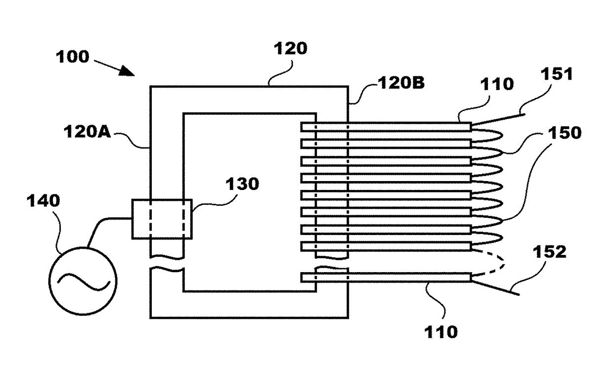
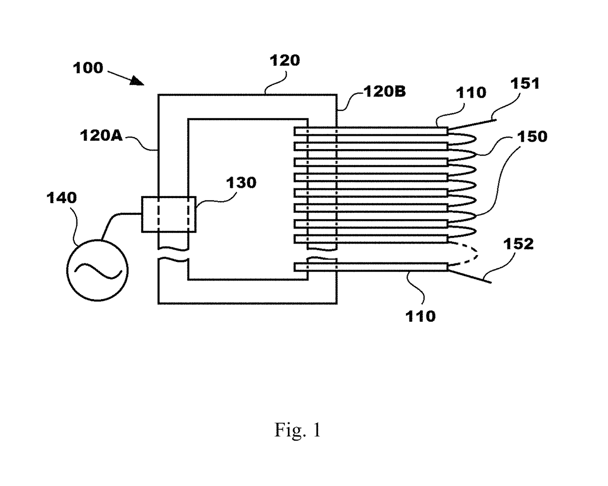
[0018]In general, as shown in FIG. 1, the high voltage pulse generator 100 consists of a transformer unit that employs a parallel stack of power switch cards 110 having series output connections 150. While the outputs of cards are connected in series 150, the cards are otherwise electrically isolated from each other. Pow...


PUM

PropertyMeasurementUnit
peak voltageaaaaaaaaaa
voltageaaaaaaaaaa
voltageaaaaaaaaaa

Abstract

A high-voltage waveform generator comprising a power source, a transformer unit comprising a magnetic core, attached to the power source, a plurality of power switch cards, each having an aperture that allows said magnetic core to pass therethrough, one or more control switches located on each power card, and a control means for actuating the control switches, a power output; wherein the power switch cards are connected in series, wherein each of the apertures in the power switch cards is surrounded by conductive windings, whereby when the power source is activated, the magnetic core induces a current in each of the conductive windings, and wherein the control means activates the control switches simultaneously in under 100 nanoseconds to generate a pulse.

Description

CROSS REFERENCE TO OTHER APPLICATIONS[0001]This application claims the benefit of U.S. Provisional Application No. 62 / 349,376, filed Jun. 13, 2016.BACKGROUND OF THE INVENTION[0002]The present invention is directed to a waveform generator that can rapidly switch high voltage, direct current on and off in nanosecond speeds to create a pulse or an alternating current.[0003]Rapid switching pulse generators are known. For example, US Patent publication 2015 / 0318846 by Prager et al. teaches a nanosecond pulser that includes one or more switch circuits including one or more solid state switches, a transformer, and an output electrically coupled with the secondary winding and may output electrical pulses having a peak voltage greater than about 1 kilovolt and a rise time of less than 150 nanoseconds or less than 50 nanoseconds.[0004]Electricity is transmitted from generators to users as high voltage alternating current. High voltage is used to minimize resistive heat loss in the transmissio...

Claims


Application Information

Patent Timeline
Patent Type & Authority Patents(United States)
IPC IPC(8): H03K3/00H01J49/02H03K3/57H03K3/02H01F27/34H02M7/539
CPCH01J49/022H01F27/34H03K3/57H03K3/02H02M7/539H01F27/40H01F2027/408
Inventor GRIEBELER, ELMER
Owner GRIEBELER ELMER
Learn More