
Control device to control direct communication among communication terminals

a control device and terminal technology, applied in data switching networks, power management, high-level techniques, etc., can solve problems such as affecting user convenience, affecting the operation of the control device, and exceeding the communication capacity of the wireless portion of the base station, so as to achieve effective utilization and maintain the effect of direct communication

Active Publication Date: 2018-05-01
SONY CORP
View PDF16 Cites 3 Cited by
  • Summary
  • Abstract
  • Description
  • Claims
  • Application Information

AI Technical Summary

Benefits of technology

[0036]According to the present technology, direct communication can be effectively utilized and maintained. It is noted that the effects described herein are not necessarily limiting, and any one of the effects described in the present disclosure may be exerted.

Problems solved by technology

In public telecommunication, increased corresponding terminals and enlarged communication traffic volumes are recently causing a squeeze on wireless connection, leading to damages to user's convenience, such as decreased communication rates and interruption of communication.
Especially in urban areas where corresponding terminals are densely used, connection is concentrated in a specific base station and therefore exceeds the communication capacity of a wireless portion of the base station, thereby failing to connect even to networks.
In each of these technologies, the number of terminals that can be connected at the same time has an upper limit.
That is, in FDMA, the number of usable frequencies is limited, and therefore the number of terminals that can be connected at the same time has an upper limit.
In TDMA, an interval between times to be allocated becomes longer as the number of terminals increases, causing decrease in communication rates.
Even with the technologies as described above, there is caused a situation where user's convenience is damaged by the limitation of multiple access due to the increased number of terminals and the concentration of terminals in recent years.
Accordingly, communication of control information itself also causes a squeeze on communication capacities.

Method used


Image

  • Control device to control direct communication among communication terminals
  • Control device to control direct communication among communication terminals
  • Control device to control direct communication among communication terminals

Examples


example 1

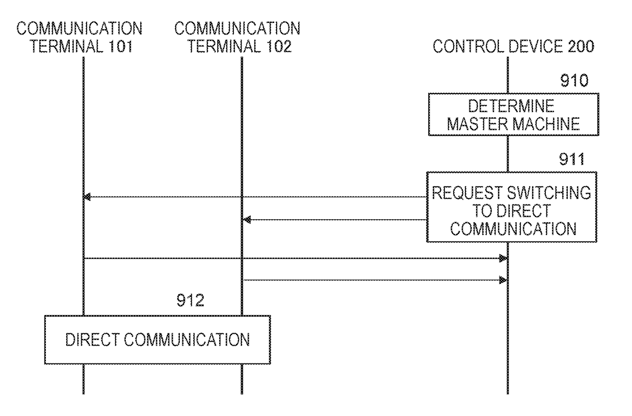
[0077]There will be described a case in which a wireless LAN is selected as a direct communication wireless system, and the roles of AP and STA are designated. For example, it is assumed that the communication terminal 101 is an access point (AP), and the communication terminal 102 is a station (STA).

[0078]The communication terminal 101 acts as an AP during a designated measurement time. Specifically, the communication terminal 101 periodically transmits a signal called a beacon in a designated frequency. This beacon is provided with a service set identifier (SSID) that is an identifier in a wireless LAN, and the SSID can be read in a receiver terminal. This beacon is also provided with a MAC address of the communication terminal 101, and the MAC address can be similarly read in a receiver terminal.

[0079]The communication terminal 102 acts as an STA during a designated measurement time. Specifically, the communication terminal 102 receives a beacon signal in a designated frequency t...

example 2

[0085]There will be described a case in which a wireless LAN is selected as a direct communication wireless system, and Wi-Fi Direct is designated. In Wi-Fi Direct, the communication terminal 101 and the communication terminal 102 have an equal role. The specifications specify that each terminal transmits a probe request, and a terminal having received this probe request offers a probe response. Accordingly, the received electric field intensity can be measured in each of the communication terminal 101 and the communication terminal 102.

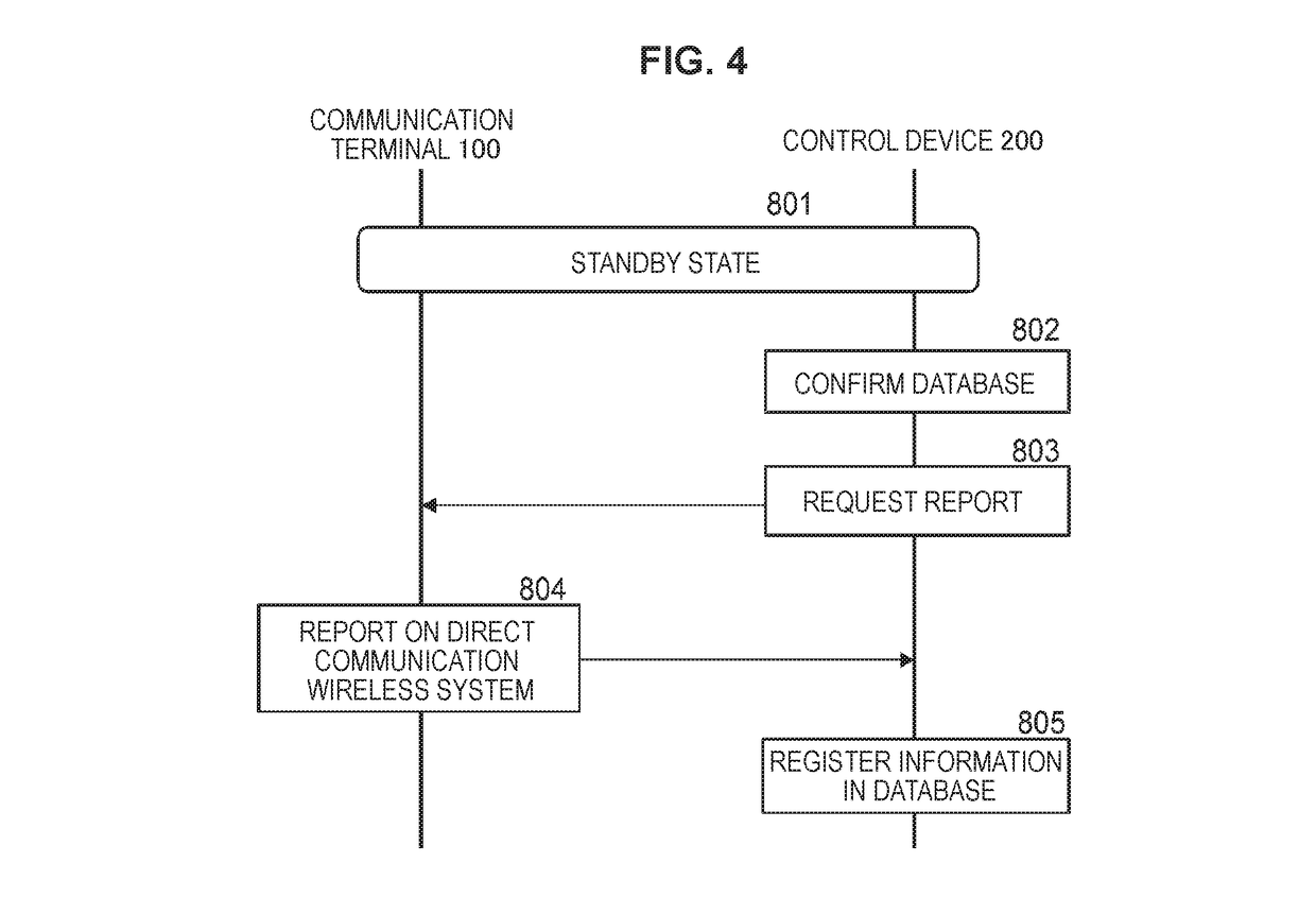
[0086]In this case, each of the communication terminal 101 and the communication terminal 102 reports the measured electric field intensity as the confirmation result to the control device 200. The control device 200 compares the electric field intensity reported from each terminal with the minimum receivable electric field intensity stored in the database 703 to judge whether direct communication is possible (step 907). It is noted that the criterio...

example 3

[0087]There will be described a case in which BT is selected as a direct communication wireless system. In BT, the specifications specify that one terminal transmits an inquiry command, and a terminal having received this inquiry command returns a reply. The communication terminal 101 and the communication terminal 102 receive an inquiry command and a reply to the inquiry command respectively, thereby to measure respective received electric field intensities.

[0088]In this case, each of the communication terminal 101 and the communication terminal 102 reports the measured electric field intensity as the confirmation result to the control device 200. The control device 200 compares the electric field intensity reported from each terminal with the minimum receivable electric field intensity stored in the database 703 to judge whether direct communication is possible (step 907). It is noted that the criterion in this case is similar to that when the measured electric field intensity is ...


PUM


Abstract

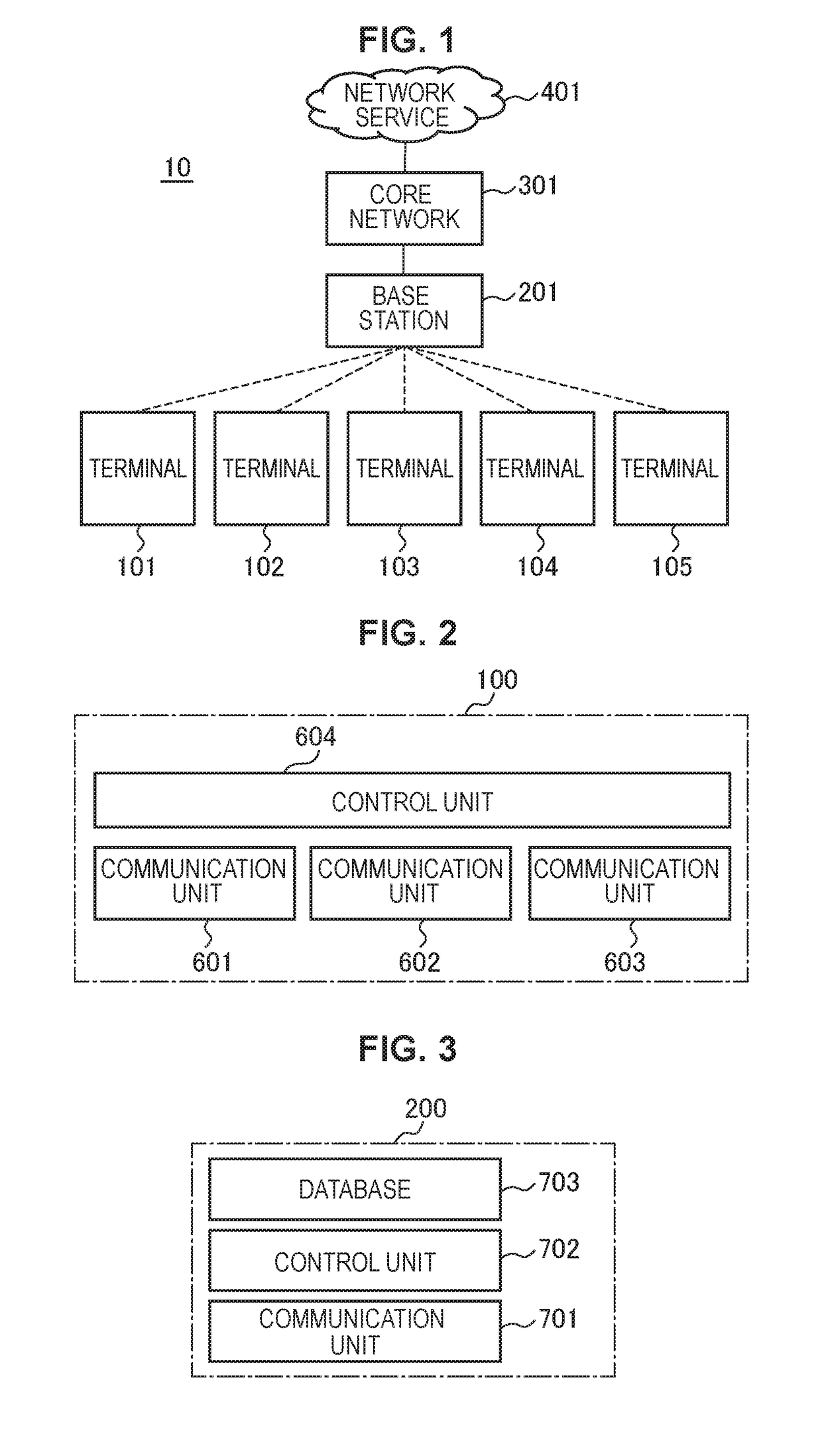
Effective utilization and maintenance of direct communication are provided.A state monitoring unit monitors a state of a predetermined number of terminal groups. Each terminal group includes a predetermined number of first communication terminals, and a second communication terminal that performs direct communication with the first communication terminals while being connected to a base station, When the state comes to fail to satisfy a certain condition, a group structure control unit changes a structure of the terminal groups. For example, the state monitoring unit monitors a communication traffic volume of data communication passing through the second communication terminal in each of the predetermined number of terminal groups. Also, for example, the state monitoring unit monitors a state (communication quality, remaining battery level, and the like) of the first communication terminal and / or the second communication terminal.

Description

TECHNICAL FIELD[0001]The present technology relates to a control device, a base station, and a communication terminal. In particular, the present technology relates to a control device that controls direct communication among terminals.BACKGROUND ART[0002]In public telecommunication, increased corresponding terminals and enlarged communication traffic volumes are recently causing a squeeze on wireless connection, leading to damages to user's convenience, such as decreased communication rates and interruption of communication. Especially in urban areas where corresponding terminals are densely used, connection is concentrated in a specific base station and therefore exceeds the communication capacity of a wireless portion of the base station, thereby failing to connect even to networks.[0003]In connection between the base station and the terminals, a technology called multiple access is generally used, enabling a plurality of terminals to be apparently connected to one base station a...

Claims


Application Information

Patent Timeline
Patent Type & Authority Patents(United States)
IPC IPC(8): H04B7/00H04L29/08H04W52/02H04L12/851H04W84/18H04W8/18H04W92/18H04W88/06
CPCH04W76/14H04W76/23H04W76/15H04L47/24H04W52/028H04W52/0277H04L67/104Y02D70/00H04W92/18H04W8/186H04W84/18H04W88/06Y02D30/70
Inventor SATO, MASANORIITOH, KATSUTOSHISUZUKI, HIDEYUKI
Owner SONY CORP
Learn More