Heater element for a vaporization device

Active Publication Date: 2018-05-15
FUNAI ELECTRIC CO LTD
View PDF3 Cites 39 Cited by
  • Summary
  • Abstract
  • Description
  • Claims
  • Application Information

AI Technical Summary

Benefits of technology

[0002]When jetting a fluid onto a heated surface it is highly desirable for 100% of the fluid to vaporize so that liquid is not discharged from the vaporizing device. The problem lies in that the vaporizing heater must be small enough to heat up extremely quickly, yet has enough surface area to catch all fluid and fluid droplets that are being ejected onto the heater element. A simple planar heater loses efficiency due to the margins of the heater not being wetted by the impinging fluid ejected onto the heater. Accordingly, the heater must be ma

Problems solved by technology

The problem lies in that the vaporizing heater must be small enough to heat up extremely quickly, yet has enough surface area to catch all fluid and fluid droplets that are being ejected onto the heater element.
A simple planar heater loses efficiency due to the margins of the heater

Method used


Image

  • Heater element for a vaporization device
  • Heater element for a vaporization device
  • Heater element for a vaporization device

Examples


Example

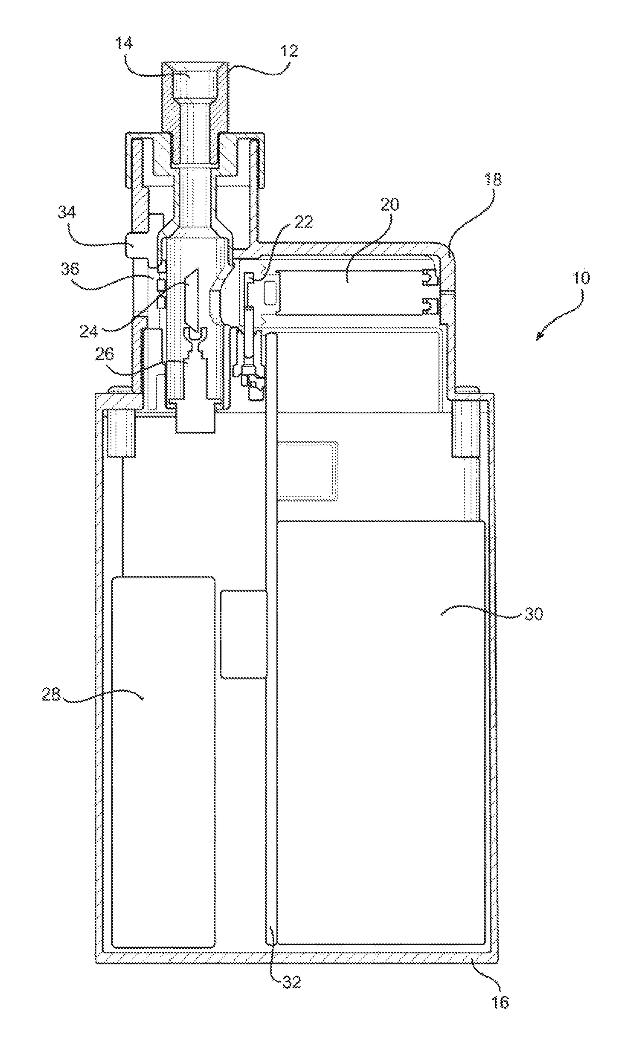
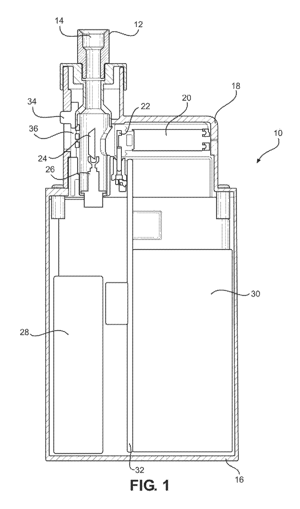
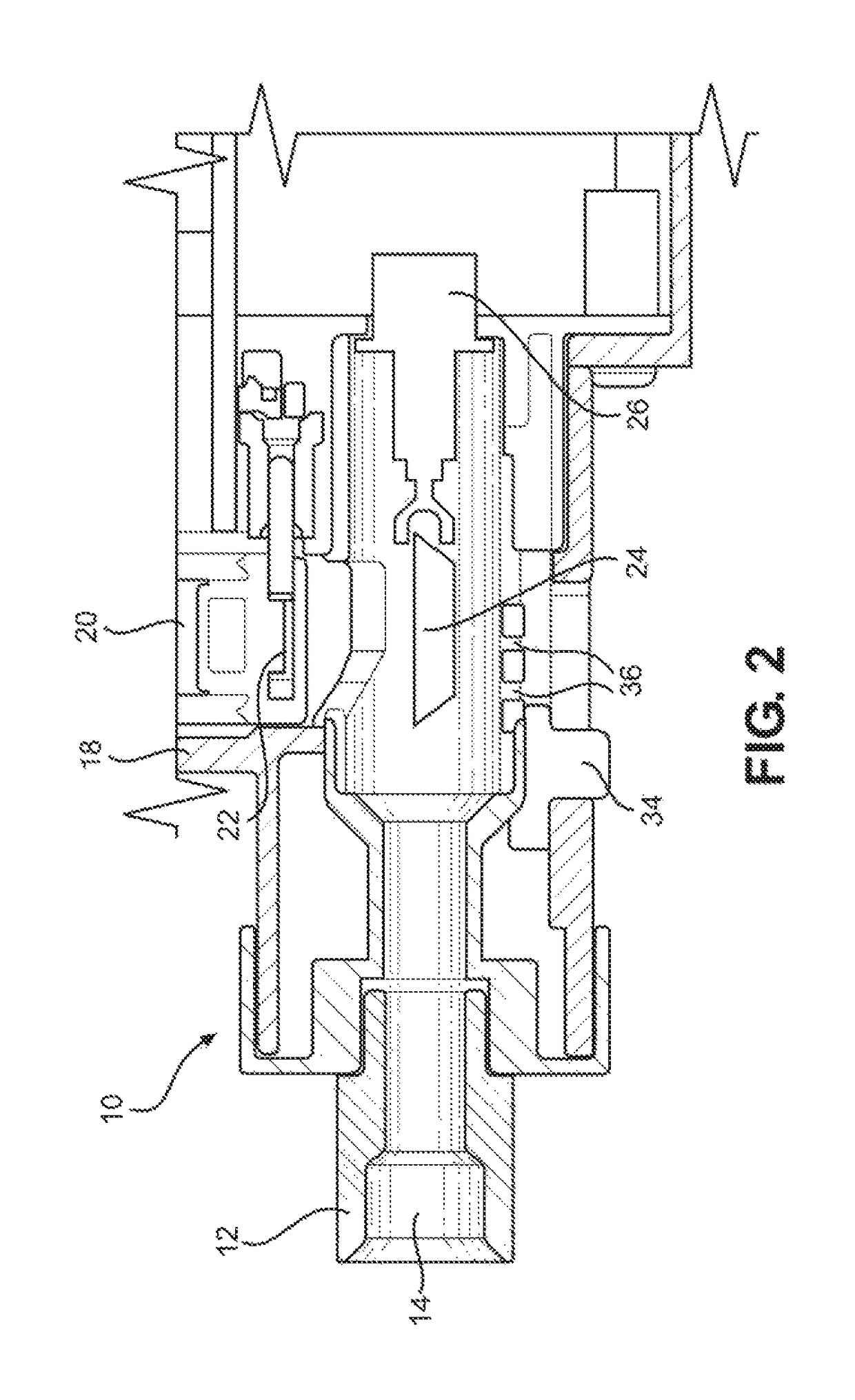
[0019]The disclosure is directed to a vaporization device 10 as shown in FIGS. 1 and 2 and heater elements therefor as shown in FIGS. 3-8. Such devices 10 may be used for a wide variety of applications wherein a liquid is ejected onto a heater element to provide a vapor stream as described in more detail below. Such devices 10 are typically hand held devices such as electronic cigarettes that have a mouthpiece 12 for inhaling vapors generated by the device 10. The mouthpiece 12 includes a conduit 14 for flow of vapors out of the device 10. The main components of the device 10 include a housing body 16, a removable cartridge cover 18, a removable fluid supply cartridge 20, an ejection head 22 associated with the fluid supply cartridge 20, and a heater element 24 for vaporizing fluid ejected from the ejection head 22 and a holder 26 providing electrical connections for the heating element 24. Other components associated with the vaporization device 10 include a rechargeable power supp...


PUM


Abstract

A heater element for a vaporizing device, a vaporizing device containing the heater element, and a method for vaporizing fluid ejected by an ejection head. The heater element includes a conductive material having a concave area. The concave area of the heater element captures and vaporizes fluid ejected from an ejection head in the vaporization device. The concave area of the heating element has a cavity volume that is at least sufficient to retain an entire volume of liquid to be vaporized.

Description

TECHNICAL FIELD[0001]One of the applications of a fluidic ejection device is to jet a solution on to another device where a secondary function may be performed. A common secondary function is to vaporize a solution using a heater such that the contents of the solution can be vaporized so as to deliver the solution as a gaseous substance. Applications of such technology include, but are not limited to, metering and vaporizing device for electronic cigarettes, vapor therapy, gaseous pharmaceutical delivery, vapor phase reactions for micro-labs, and the like. A problem associated with such devices is efficient vaporization of the fluid. This document discloses improved heater elements and methods for improving the vaporization efficiency of heater elements for vaporization devices.BACKGROUND AND SUMMARY[0002]When jetting a fluid onto a heated surface it is highly desirable for 100% of the fluid to vaporize so that liquid is not discharged from the vaporizing device. The problem lies in...

Claims


Application Information

Patent Timeline
IPC IPC(8): A24F17/00A24F47/00H05B3/12A24F40/10A24F40/46
CPCA24F47/008H05B3/12H05B2203/021H05B3/06H05B3/44H05B2203/022A24F40/46A24F40/10
Inventor BELL, BYRON V.
Owner FUNAI ELECTRIC CO LTD
Why Eureka
Try Eureka