Slick line, fiber optic cable or tubing wellbore pulling tool and propulsion module

a fiber optic cable or tubing wellbore technology, applied in the direction of wellbore/well accessories, earthwork drilling and mining, construction, etc., can solve the problems of no special-designed pulling tool, fiber optic cable is very thin and weak, and the same challenges are encountered, so as to achieve high gear ratio, strong and efficient

Active Publication Date: 2020-09-15
WELL CONVEYOR AS
View PDF6 Cites 0 Cited by
  • Summary
  • Abstract
  • Description
  • Claims
  • Application Information

AI Technical Summary

Benefits of technology

[0008]As compared to a planetary gear solution of the same size, this invention provides a gear ratio that is 5-10 times higher within the same dimensions.
[0013]In the present invention, a high efficiency, high RPM, low torque, submergible brushless motor can be used which exhibits good moisture resistance and wear resistance and that does not lose power and efficiency over time. This is enabled through the use of a gear system in the propulsion wheel, which gear system includes an eccentric, internally toothed gear system in the form of a hypocycloid gear, or a cycloid gear exhibiting a rated transformer ratio and an output torque that is significantly larger than what can be achieved with a planetary gear of the same size.

Problems solved by technology

In itself, a fiber optic cable is very thin and weak.
Common to all these cables are that they are very lightweight and a bit flexible, which present some challenges when they are to be installed in horizontal wells.
Currently, no pulling tool exists that is specially designed for these applications.
Similarly to a fiber optic cable, the same challenges are encountered when a slick line is run into horizontal wells.
Due to the limited rigidity of the slick line, it is not possible to push it very far into horizontal wells.
Such a system is technically complex and not very efficient.
Such systems present a challenge in that the gear ratio is not high enough to allow the use a high efficiency, brushless permanent magnet motor operating at a relatively high revolutions per minute (RPM).
However, there is a limitation on how small a planetary gear can be made since such a gear includes a number of components located inside each other, each of which needs to resist the torque applied.
Also, the achievable gear ratio is relatively low.

Method used


Image

  • Slick line, fiber optic cable or tubing wellbore pulling tool and propulsion module
  • Slick line, fiber optic cable or tubing wellbore pulling tool and propulsion module
  • Slick line, fiber optic cable or tubing wellbore pulling tool and propulsion module

Examples


Embodiment Construction

[0045]The invention will now be explained in more detail using a cycloid gear, with reference to the drawings:

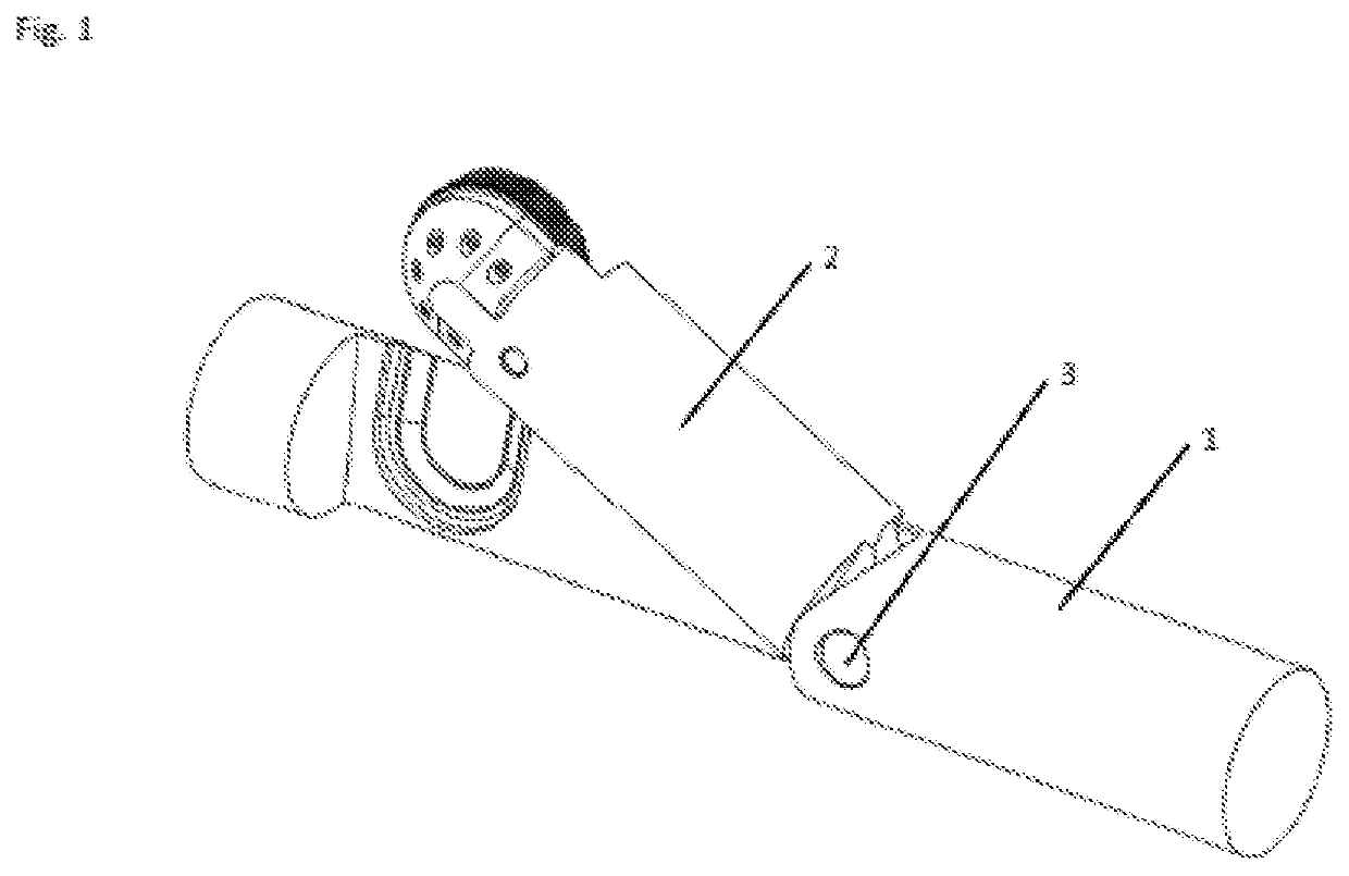
[0046]FIG. 1 is a perspective view of an embodiment of a pulling assembly according to the present invention. The pulling assembly includes a main section 1 supporting a complete propulsion arm 2. The complete propulsion arm 2 is connected to main section 1 via a hinge joint 3 by way of which the complete propulsion arm 2 can be tilted outwards.

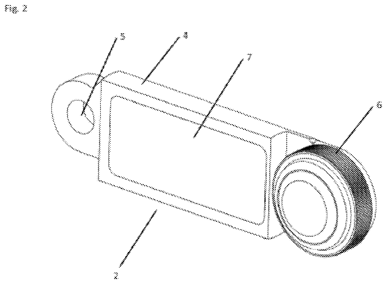
[0047]FIG. 2 shows the complete propulsion arm 2 comprising an arm body 4, a pivoting hole 5, the drive mechanism of FIG. 3, a complete propulsion wheel 6 and a cover 7.

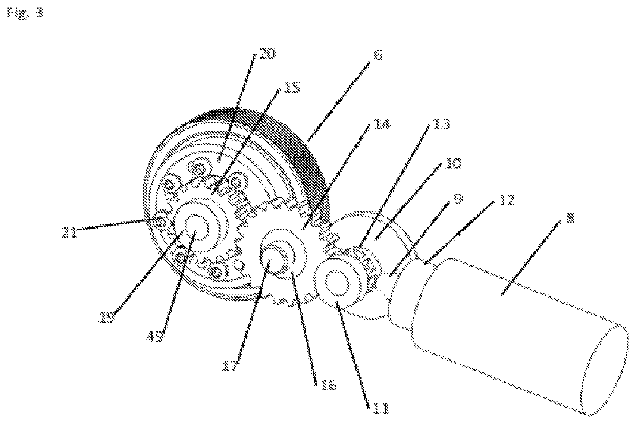
[0048]FIG. 3 shows the drive mechanism comprising a motor 8, an angular gear which includes a pinion 9 fixed to the drive shaft of the motor, and a crown gear 10 supported in arm body 4 (shown in FIG. 2) by way of a bearing 11. Pinion 9 is supported in arm body 4 (shown in FIG. 2) by way of a bearing 12. Crown gear 10 is connected to a straight toothed wheel 13 connect...


PUM


Abstract

A slick line, fiber optic cable, or tubing wellbore pulling tool includes a propulsion module having a main section and a hinged propulsion arm. A propulsion wheel with a gear system is supported in the propulsion arm. A gear system of the propulsion wheel includes an eccentric, internally toothed gear system with a fixed inner gear and a movable outer gear. The movable outer gear constitutes the propulsion wheel. An electric motor is configured to drive the propulsion wheel via the gear system.

Description

BACKGROUND OF THE INVENTION1. Field of the Invention[0001]The present invention relates to a pulling tool and to a propulsion module of a pulling tool used for pulling itself and other equipment into a wellbore or tubing.2. Description of Related Art[0002]Wellbores and tubing typically include long vertical and horizontal runs. In many wells there is a need for installing a fiber optic cable to obtain real-time measurements of flow, pressure, and temperature, among other things. In itself, a fiber optic cable is very thin and weak. Therefore, several types of claddings are used for protecting the fiber optic cable such as metal, Kevlar, or carbon rods. Common to all these cables are that they are very lightweight and a bit flexible, which present some challenges when they are to be installed in horizontal wells.[0003]Since a fiber optic cable is a signal cable only, most pulling tools need to be battery operated. Therefore, it is essential that the pulling tool is as efficient and l...

Claims


Application Information

Patent Timeline
Patent Type & Authority Patents(United States)
IPC IPC(8): E21B23/14E21B4/00E21B4/18E21B23/00
CPCE21B4/18E21B4/006E21B23/14E21B23/001
Inventor FUGLESTAD, KENNETH
Owner WELL CONVEYOR AS
Why Eureka
Try Eureka