Fabrication of high efficiency, high quality, large area diffractive waveplates and arrays

a technology of diffractive waveplates and arrays, which is applied in the field of fabrication of oneor twodimensional diffractive waveplate can solve the problems of inability to achieve high-quality dws and their arrays in large area, inability to use high-quality dws and their arrays in large-scale production, and inability to produce micro-scale-period gratings with diffractive properties at optical wavelengths. high efficiency and low cos

Active Publication Date: 2018-05-29
BEAM ENG FOR ADVANCED MEASUREMENTS
View PDF123 Cites 21 Cited by
  • Summary
  • Abstract
  • Description
  • Claims
  • Application Information

AI Technical Summary

Benefits of technology

[0020]Thus, the objective of the present invention is providing means for fabricating high quality DWs in large area, typically exceeding 1″ in sizes, in large quantities, high yield, low cost.

Problems solved by technology

A critically important issue for producing LC orientation patterns at high spatial frequencies is their mechanical stability.
While acceptable for research and development purposes, none of the techniques known in the prior art can be used for fabricating high quality DWs and their arrays in large area, inexpensively, and in high volume production.
Thus, such a grating modulated polarization of the output light at macroscopic scales and could not be used for production of microscale-period gratings with diffractive properties at optical wavelengths.

Method used


Image

  • Fabrication of high efficiency, high quality, large area diffractive waveplates and arrays
  • Fabrication of high efficiency, high quality, large area diffractive waveplates and arrays
  • Fabrication of high efficiency, high quality, large area diffractive waveplates and arrays

Examples


Embodiment Construction

[0034]Before explaining the disclosed embodiment of the present invention in detail it is to be understood that the invention is not limited in its application to the details of the particular arrangement shown since the invention is capable of other embodiments. Also, the terminology used herein is for the purpose of description and not limitation.

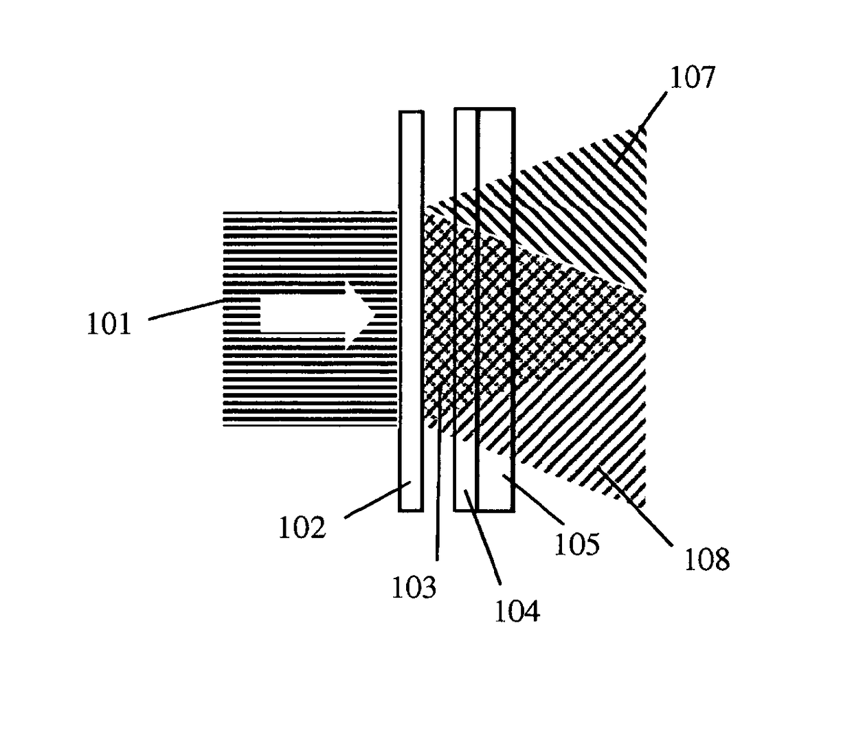
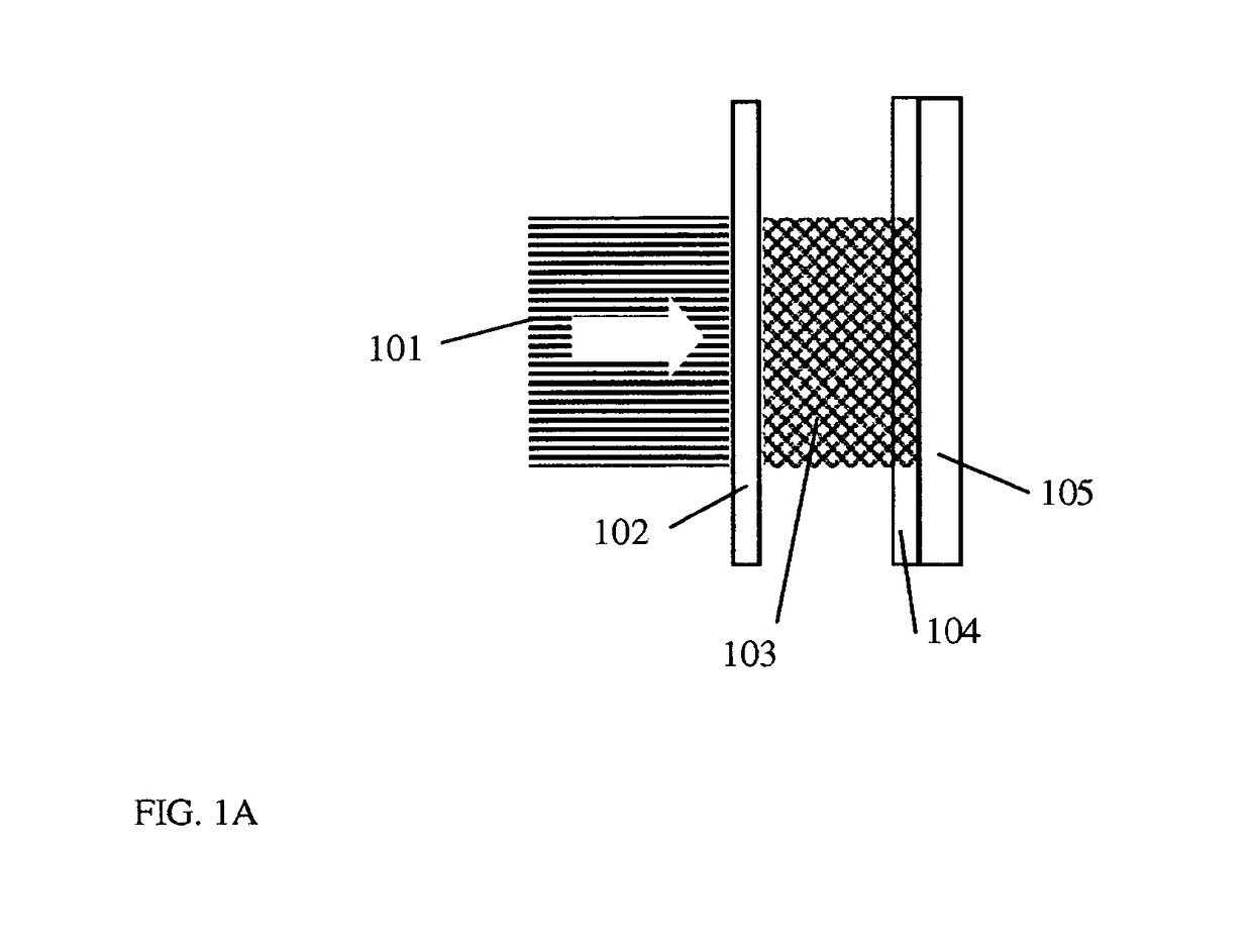
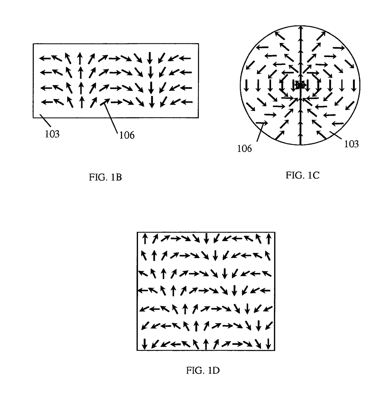
[0035]The preferred embodiment of the present invention shown in FIG. IA includes a light beam 101 incident upon an optical component 102 capable of converting the incident light beam 101 into a beam with spatially continuous modulated polarization pattern 103. Of particular interest are “cycloidal” and axial modulation patterns shown schematically in FIG. IB and FIG. IC, correspondingly, wherein the numerals 106 indicate the linear polarization direction at each point of the plane at the output of the polarization converter (S. R. Nersisyan, et al., “Characterization of optically imprinted polarization gratings,” Appl. Optics 48, 4062, 2...


PUM

PropertyMeasurementUnit
diameteraaaaaaaaaa
sizeaaaaaaaaaa
sizesaaaaaaaaaa

Abstract

An apparatus and method for fabricating high quality one- or two-dimensional diffractive waveplates and arrays that exhibit high diffraction efficiency and capable of inexpensive large volume production. A generally non-holographic and aperiodic polarization converter for converting the polarization of a coherent input light beam of a visible wavelength into a pattern of continuous spatial modulation at the output of the polarization converter. A photoresponsive material characterized by an anisotropy axis according to polarization of the light beam is exposed to a polarization modulation pattern and coated subsequently with an anisotropic material overlayer with ability of producing an optical axis orientation according to and under the influence of the anisotropy axis of the photoresponsive material layer. The diffractive waveplates are obtained when exposure time of photoresponsive material layer exceeds an order of magnitude the time period that is known to produce spatially homogeneous orientation of the anisotropic overlayer.

Description

CROSS REFERENCE TO RELATED APPLICATION[0001]This application is a continuation in part of U.S. patent application Ser. No. 13 / 860,934, entitled “Fabrication of High Efficiency, High Quality, Large Area Diffractive Waveplates and Arrays”, filed Apr. 11, 2013 which is, in turn, a continuation of U.S. patent application Ser. No. 12 / 662,525, entitled “Fabrication of High Efficiency, High Quality, Large Area Diffractive Waveplates and Arrays”, and filed Apr. 21, 2010.STATEMENT REGARDING FEDERALLY SPONSORED RESEARCH OR DEVELOPMENT[0002]This invention was made with Government support under Contract No. W911QY-07-C-0032.RIGHTS OF THE GOVERNMENT[0003]The invention described herein may be manufactured and used by or for the Government of the United States for all governmental purposes without the payment of any royalty.FIELD OF THE INVENTION[0004]This invention relates to fabrication of one- or two-dimensional diffractive waveplates and their arrays, those waveplates including “cycloidal” dif...

Claims


Application Information

Patent Timeline
Patent Type & Authority Patents(United States)
IPC IPC(8): G03H1/10G03F7/20G02B5/30G02B5/32G03H1/04
CPCG03F7/20G02B5/3083G02B5/32G03H2260/51G03H2001/0439
Inventor TABIRIAN, NELSON V.NERSISYAN, SARIK R.KIMBALL, BRIAN R.STEEVES, DIANE M.
Owner BEAM ENG FOR ADVANCED MEASUREMENTS
Why Eureka
Try Eureka